I am continuing our dialogue
http://www.diyaudio.com/forums/showthread.php?postid=1752991#post1752991
here, not to hijack the original thread.
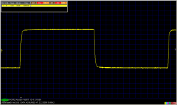
No output coil, you are right. I will make more measurements of this kind with suggested load later, as I am pretty busy right now. I promise to return to these mesurements. As a reminder, the original response into 4 ohm.
http://www.diyaudio.com/forums/showthread.php?postid=1752991#post1752991
here, not to hijack the original thread.
No output coil, you are right. I will make more measurements of this kind with suggested load later, as I am pretty busy right now. I promise to return to these mesurements. As a reminder, the original response into 4 ohm.
Attachments
http://www.diyaudio.com/forums/showthread.php?postid=1575583#post1575583
Uses massive feedback, though. And to add insult to injury, I can't use it to heat my house .
.
Uses massive feedback, though. And to add insult to injury, I can't use it to heat my house
.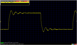
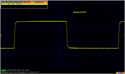
PMA said:Okay, 10kHz square into 5 ohm//1uF :
(no output coil)
30V/div vertical???????
3V/div vertical, in all the images shown. If there is 30V/d somewhere, it is a forgotten probe scale factor.
ACD said:I think syn08 is looking at the Vpk-pk 😉
No, in the 1st image (5R//1uF) I really forgot to switch off the probe scale factor.
This got going because I mentioned that I would like to see exactly these sorts of images with projects that have been built...
I may be foolish but it gives me another "vector" on the performance of any given amp. Beyond the simulations, and beyond the "specs", I like to see what the square wave response looks like into this sort of range of loads...
Dat's all.
_-_-bear
I may be foolish but it gives me another "vector" on the performance of any given amp. Beyond the simulations, and beyond the "specs", I like to see what the square wave response looks like into this sort of range of loads...
Dat's all.
_-_-bear
As you can see, probably no one would show us similar kind of measurements.
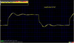
I should note that I measured at power amp speaker terminals, i.e. there is about 20cm of wires from PCB board to speaker terminal, and ringing seen in 1uF and 4.7uF load is that of the inductance of connecting wire and the cap.
I should note that I measured at power amp speaker terminals, i.e. there is about 20cm of wires from PCB board to speaker terminal, and ringing seen in 1uF and 4.7uF load is that of the inductance of connecting wire and the cap.
Oh?
Without the inductance and just the cap, less or no ringing?
Syn08 shows us via a link his amp at 500kHz showing some overshoot, but at 500kHz. I am wondering how that squarewave looks back down at 10kHz?
I would be happy to show my Symphony No.1 amplifier (circa 1990 design) but I don't have the amp (128lbs) and my antique test gear within striking distance of each other that this time. 🙁
Once the weather lightens up here a bit, and assuming I have some extra time, and manage to think of it, I'll shoot some similar pictures... Don't think I'll look as good, and I'm not currently in possession of a square wave gen that is worth a damn at 10kHz anyhow (pathetic, eh?), I've used the Tek's calibrator out for a good fast 1kHz. up till now...
Could use some moderne test gear... any donatations? 😀
_-_-bear
Count with me. 400 nH of wire inductance, 4u7 cap. We see the resonant frequency.
I would like to see syn08's amplifier loaded by 1uF and 4.7uF, at 20 - 30Vpp. With 47nF, that is close to 100nF in syn's measurement, I have almost no ringing.
I would like to see syn08's amplifier loaded by 1uF and 4.7uF, at 20 - 30Vpp. With 47nF, that is close to 100nF in syn's measurement, I have almost no ringing.
No disagreement.
I am not in a contest with anyone, nor in a competition to see whose amplifier is "best". Or for who is the smartest. I'll leave that to others. I'm just a traveller down this path who is fascinated by the subtlety in all that we do electronically and sonically. 😀
The real world type loads imho are very important, since in most real world speakers there is not a purely resistive load (a few exceptions out there), so we care what an amplifier will do in those cases. At least I care.
But I would like to see this sort of real world test image for any and all of the project amps that folks would care to provide - including examples of commercial amps (as a reference point and baseline). 😀
_-_-bear
PMA said:Count with me. 400 nH of wire inductance, 4u7 cap. We see the resonant frequency.
I would like to see syn08's amplifier loaded by 1uF and 4.7uF, at 20 - 30Vpp. With 47nF, that is close to 100nF in syn's measurement, I have almost no ringing.
I would love to see that too, unfortunately I don't think it's possible. Short of the cap ESR and wiring, it is only the output impedance that limits the current through a capacitive load. As it is, anything over 100nF or 10Vpp triggers the overcurrent protection, set to about 24A. The final implementation as in the pictures on my web site has a 0.7uH output coil. With that I can go as high as 2uF||4ohm for 30Vpp @100KHz.
Your no feedback amp has much higher output impedance, which explains the allowed higher output voltage and the dampened response in high capacitive loads.
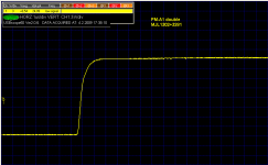
At 10KHz the response is perfectly square with a rise/fall times of about 50nS
- Status
- Not open for further replies.
- Home
- Amplifiers
- Solid State
- About power amp step response etc. :-)