After a successful design of a high power bass amp with GU50 I wanted to find out some nonstandard application possibilities and limits for this tube in UL mode . The resulting application might be useable for a bass amp again or a hifi power stage. I want to share the results here. It is a translated short summary of my contributions to that topic posted in this German FORUM . It might be interesting for some of you.
First let us have a look to the tube itself. It is a “real old style pentode”; the screen grid (G2) is not in the shadow of the control grid as in beam power pentodes. What is the consequence? If the plate voltage is lower than the G2 voltage than the G2 current in much higher than in a beam power pentode like KT88. Taking into account the maximum allowed G2 power dissipation we can expect a lower maximum G2 voltage than e.g. for a KT88. Looking to available application data from LS50, E/FL152 and GU50 (they are all the same type of pentode except for the heater voltage) here are some observations which confirms this assumption:
1. In PP pentode mode up to a plate supply (Ub) of 400V the G2 voltage (Ug2) is limited to 250V
2. In PP pentode at Ub=600V/800V Ug2 is limited to 300V
3. In PP Triode mode Ub= 400V is allowed
4. In a LS50 report there have been shown static data values for triode mode with Ua/Ug2= 800V
Some conclusions/observations
- For higher Ub (basically > 300V) we need a separate UL winding for G2)
- Ug2 up to 800V is possible
Using these constraints I have made a test circuit with a PP UL OT having a separate screen winding (20%/40%). MOSFET drivers allow to drive the powerstage with AB2. The plate supply (Ub) is 800V, the screen supply is switcheable between 400V and 600V.
The results:
Case 1) (moderate)
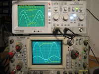
Ub=800V, Ug2=400V,Raa 7K8,UL=20%, AB2 with NFB. The output power is about 120W.
G2 is not going red what I have expected. The first scope picture is showing the result:
- at the upper scope : Ug1 and Output at 7,8 Ohm
- at the scope below: Ua and Ug2
You can see on the scope picture the voltage ratio between the plate voltage (Ua) and Ug2 caused by the UL mode. The duration of Ua <Ug2 is limited, as well as the voltage difference.
Case 2) (aggressive)
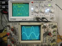
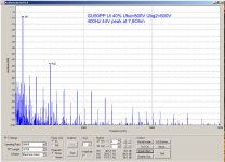
Ub=800V, Ug2=600V,Raa 7K8,UL=40%, AB1 with NFB. The output power is about 120W.
A scope picture and a distortion measurements are attached. Again G2 is not going red, as long as we are at AB1. (Ug1max=0V). I have done some “duration tests”, several hours running at full power. The power stage has shown stable behavior.
I personally might use case 1) in a bass amp and case 2) in hifi applications. I know that an UL OT with separate G2 winding has some obstacles (cost, complexity etc…). For myself I have learnt something about screen behavior of the GU50 in UL applications with separate screen supply. Looking to tubes still in production: I would expect a comparable behaviour shown above if I would do the test with EL34 – as long as the tube are from a reliable manufacturer.
Hans- Georg
First let us have a look to the tube itself. It is a “real old style pentode”; the screen grid (G2) is not in the shadow of the control grid as in beam power pentodes. What is the consequence? If the plate voltage is lower than the G2 voltage than the G2 current in much higher than in a beam power pentode like KT88. Taking into account the maximum allowed G2 power dissipation we can expect a lower maximum G2 voltage than e.g. for a KT88. Looking to available application data from LS50, E/FL152 and GU50 (they are all the same type of pentode except for the heater voltage) here are some observations which confirms this assumption:
1. In PP pentode mode up to a plate supply (Ub) of 400V the G2 voltage (Ug2) is limited to 250V
2. In PP pentode at Ub=600V/800V Ug2 is limited to 300V
3. In PP Triode mode Ub= 400V is allowed
4. In a LS50 report there have been shown static data values for triode mode with Ua/Ug2= 800V
Some conclusions/observations
- For higher Ub (basically > 300V) we need a separate UL winding for G2)
- Ug2 up to 800V is possible
Using these constraints I have made a test circuit with a PP UL OT having a separate screen winding (20%/40%). MOSFET drivers allow to drive the powerstage with AB2. The plate supply (Ub) is 800V, the screen supply is switcheable between 400V and 600V.
The results:
Case 1) (moderate)
Ub=800V, Ug2=400V,Raa 7K8,UL=20%, AB2 with NFB. The output power is about 120W.
G2 is not going red what I have expected. The first scope picture is showing the result:
- at the upper scope : Ug1 and Output at 7,8 Ohm
- at the scope below: Ua and Ug2
You can see on the scope picture the voltage ratio between the plate voltage (Ua) and Ug2 caused by the UL mode. The duration of Ua <Ug2 is limited, as well as the voltage difference.
Case 2) (aggressive)
Ub=800V, Ug2=600V,Raa 7K8,UL=40%, AB1 with NFB. The output power is about 120W.
A scope picture and a distortion measurements are attached. Again G2 is not going red, as long as we are at AB1. (Ug1max=0V). I have done some “duration tests”, several hours running at full power. The power stage has shown stable behavior.
I personally might use case 1) in a bass amp and case 2) in hifi applications. I know that an UL OT with separate G2 winding has some obstacles (cost, complexity etc…). For myself I have learnt something about screen behavior of the GU50 in UL applications with separate screen supply. Looking to tubes still in production: I would expect a comparable behaviour shown above if I would do the test with EL34 – as long as the tube are from a reliable manufacturer.
Hans- Georg
Attachments
-
 20130506 GU50 PP UL 20% Uba 800V Ubg2 400V 313Hz Ug1peak 16V with text small .jpg270.5 KB · Views: 828
 -
 20130509 GU50 PP UL 40% Uba 800V Ubg2 600V 400Hz Ug1peak 0V with text small.jpg276.2 KB · Views: 794
 -
 20130520 GU50 PP UL 40% Uba 800V Ubg2 600V 400Hz 44Vpeak 7,8Ohm Spectrum with text.JPG163 KB · Views: 804
Hopefully wavebourne will chime in quickly, he's the guy around here I suspect who knows just about all there is to know about this tube.
There are some type of GU50, somes are very stable, the others are fragile.
What type/ date code of GU50 are you using ?
G2 is supplied by separate regulator voltage ?
What type/ date code of GU50 are you using ?
G2 is supplied by separate regulator voltage ?
The date codes of the tubes in use are 89 09 and 90 03. I have more of them , in addition some with the date code 90 04.
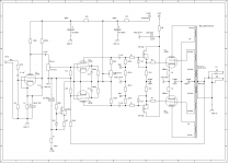
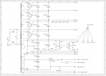
You will find the schematic of the evaluation hardware below. The power supply has a 4 rail structure (200V/400V/600V/800V)including a 5x20V 5W Zenerdiode group. This allows to change the screen voltage in steps of 100V.
The powerstage has a differential stage with EF86 and CCS enabling high peak to peak driver voltage The next stage is then a MOSFET follower to be able drive the power tubes into AB2.
HG
Attachments
Dear Hans- Georg,
have you done further tests of those two working points?
I've also seen your thread here: Bass Power Amp with GU50
and it seems the best ampto implement the shunt feedback "à la Baby Huey" with GU50, being 3 in parallel for each side, so increasing their gm and reducing their rp, giving more "space" for the shunt to work.
Have you ever tried it on that amp?
Are those transformers still available from the supplier?
Thank you
Roberto