Hi to everybody, 🙂
I just found an Onkyo tuner T-4970. It's from the 92-95 years, and it's pretty good, it was not far from the very top Onkyo tuners.
I have a few questions about it :
- On the main board there's a heat mark (a brown area) under the resistors R904 (3W) and R905 (2W). Can it be normal ?
- There are few OPA in this tuner :
NJM4560D
NJM4560D-X
NJM4558D-X
and I think we can find better now. Can I replace some of them with newer, better ICs, but without changing the component values? I have tools to measure electrical values, but RF is another world... (I have some BB OPA2604AP in my drawer)
- Final thought, are there any capacitors in the signal path worth changing for better ones? Almost all capacitors in this tuner are Sanyo, not Nichicon or Elna...
This is also a message for SinGun especially, I could read he owns this tuner, he likes it and he tweaked it too 😉
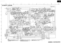
The service manual can be found here :
https://archive.org/details/manual_T4970_SM_ONKYO_EN
Thank you, have a nice week-end ! 🙂
I just found an Onkyo tuner T-4970. It's from the 92-95 years, and it's pretty good, it was not far from the very top Onkyo tuners.
I have a few questions about it :
- On the main board there's a heat mark (a brown area) under the resistors R904 (3W) and R905 (2W). Can it be normal ?
- There are few OPA in this tuner :
NJM4560D
NJM4560D-X
NJM4558D-X
and I think we can find better now. Can I replace some of them with newer, better ICs, but without changing the component values? I have tools to measure electrical values, but RF is another world... (I have some BB OPA2604AP in my drawer)
- Final thought, are there any capacitors in the signal path worth changing for better ones? Almost all capacitors in this tuner are Sanyo, not Nichicon or Elna...
This is also a message for SinGun especially, I could read he owns this tuner, he likes it and he tweaked it too 😉
The service manual can be found here :
https://archive.org/details/manual_T4970_SM_ONKYO_EN
Thank you, have a nice week-end ! 🙂
Attachments
Last edited:
Hi,
The T4970 seems to be a downgraded version of T9090 - for this reason, it is better if you check/compare their schematics.
1. Let's start with the heat: both ICs, Q902 and Q903 are better if you mount them to the backside plate for better heat dissipation. I changed the resistors R904 to 5W with the same value, R905 to 3W type, but its value was increased from 150 ohms to 180 ohms. I calculated the current through the R904 - it is the same as what is written in the service manual, 400mA.
2. Regarding opamps: yes, the BB OPA2604AP is a good choice.
3. Based on schematis, the noise from supply lines can be decreased by inserting 2.2uH instead of 10 ohms resistors: R102, R111, R118, R123 and R128.
4. Capacitors from the signal path: C404, C409, C410, C423, C424 - in all positions, I used 47uF/25V Nichicon Muse bipolar, but you can also try the Fine Gold.
Hi,
Additionally, if you enjoy listening to the AM or would like to get a better tuner, you can make the following adjustments or improvements:
5. I use a ring-ferrite with two coils wound in the opposite direction with a minimum 11mH inductance as my EMI filter before the transformer. On each side, I use a 1-1 pack of capacitors made up of 0.1uF/630Vdc mpp, 2.2nF/3kVac ceramic, and 1uF/630Vdc mpp. This can reduce the noise produced by switching supplies of mobile phones, laptops, and LED bulbs.
6. Install a 2.2 nF parallel to the main switch.
7. In essence, I replaced every electrolytic: ELNA SilmicII was used in the audio area and MPX, and dry electrolytics were used in the RF sector and digital part.
OK, thank you for all these informations !
I never listen AM, but I will follow the advices in your first post. A last question : can we use IC supports (of good quality) to mount the OPAs on them, or is it something to avoid, for cases of parasites or distortions?
I never listen AM, but I will follow the advices in your first post. A last question : can we use IC supports (of good quality) to mount the OPAs on them, or is it something to avoid, for cases of parasites or distortions?
If you use IC socket, should be the best quality. At audio output (just this IC has meaning to change), I prefer to use the LM4562, but you should try which is more suitable for your system.