I fully understand. I saw that you were wandering among several single stage phono preamp that were 30 years or older. I think that it may be easier for you to find what you want using more modern design.Hello
Thank for that nice offer. But for a long time I can only do circuit simulations, I have to repair my turntable and completely remake my power amp, and I have to do heavy repairs in my house basement.
So, I have to pass for your offer.
Thank
Bye
Gaetan
Pretending that C3 is infinite and the op-amp has infinite gain:
R1 ~= 7.254782609 kohm
C1 ~= 10.33800791 nF
R2 ~= 89.94521739 kohm
C2 ~= 35.35485368 nF
R3 = 100 ohm
R4 = 400 ohm
R5 ~= 564.4530074 ohm
C4 = 6.8 nF
I'll leave it up to you how you want to round this to practical values. If you want to keep the number of capacitors to the minimum, you could round the capacitances to 10 nF and 33 nF, scale up all resistances except R5 by a factor of 1.052412462 and then round them to the nearest E96 values.
By the way, compared to the more conventional approach of using an OPA627, this version has the advantage of having about five times as much loop gain at all audible frequencies.
So my suggested rounded values for the circuit of post 22 would be:
R1 = 7.68 kohm or 7.5 kohm (I'm not sure which is best; doing the scaling I suggested results in 7.68 kohm but with 7.5 kohm the second RIAA pole is exactly where it should be)
C1 = 10 nF
R2 = 95.3 kohm
C2 = 33 nF
R3 = 105 ohm
R4 = 422 ohm
R5 = 562 ohm
C4 = 6.8 nF
C3 = couple of uF
R6 = 100 kohm or so
Last edited:
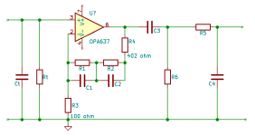
So my suggested rounded values for the circuit of post 22 would be:
R1 = 7.68 kohm or 7.5 kohm (I'm not sure which is best; doing the scaling I suggested results in 7.68 kohm but with 7.5 kohm the second RIAA pole is exactly where it should be)
C1 = 10 nF
R2 = 95.3 kohm
C2 = 33 nF
R3 = 105 ohm
R4 = 422 ohm
R5 = 562 ohm
C4 = 6.8 nF
C3 = couple of uF
R6 = 100 kohm or so
Hello
I have done a simulations of your phono circuit, the result are good and the slew rate are better than the one in post # 10.
It can take long before I can do prototypes of those phonos circuits, but thank for your help.
Bye
Gaetan
- Home
- Source & Line
- Analogue Source
- About a phono preamp and decompensated op amp