Hi guys:
Just started building a 300B SE, the original design connect +5VDC to one filament, and the other to ground.
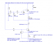
I want to implement a Coleman regulator, apparently I can't connect one filament to GND, which shorts the CCS part of the regulator.
Can I just connect F+/F- to both sides of filament without grounding? or any filament resistor needed?
Cheers
Attachments
Off the top of my head, I don't see a way to make the existing sockets on the TSE board compatible with that ^^^^^.
If you were really determined, build a socket adapter, or move the sockets off the pcb so the filaments can be isolated from the existing board. Both "solutions" could present additional problems that would have to be worked through.
I would get the TSE board working correctly in it's stock configuration before I tried a major modification ^^^^ like that. It's already DC regulated. You may be seeking a solution to a non existent problem.
Win W5JAG
Off the top of my head, I don't see a way to make the existing sockets on the TSE board compatible with that ^^^^^.
If you were really determined, build a socket adapter, or move the sockets off the pcb so the filaments can be isolated from the existing board. Both "solutions" could present additional problems that would have to be worked through.
I would get the TSE board working correctly in it's stock configuration before I tried a major modification ^^^^ like that. It's already DC regulated. You may be seeking a solution to a non existent problem.
Win W5JAG
Oh, I build this TSE on my own, basically I experimentally separate them into PSU and Mainboard, so that won't be an issue.
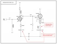
After reading, I think what I meant is "bias resistor", the TSE put 5V into 300B then grounded.
What I want to ask, is that with Coleman's Reg, any filament resistor or cathode resistor needed? Like figure below?
Thank you,
erik
Attachments
The TSE output stage is fixed bias.
Maybe questions about the specific implementation of that filament regulator would be better addressed to its vendor / designer?
I would strongly encourage you to get the TSE working in completely stock configuration before you attempt to modify it.
Win W5JAG
edit: most (all ? ) TSE builders use the 10 ohm resistor in the plate leads to measure current through the output tubes.
Last edited:
- Status
- Not open for further replies.

