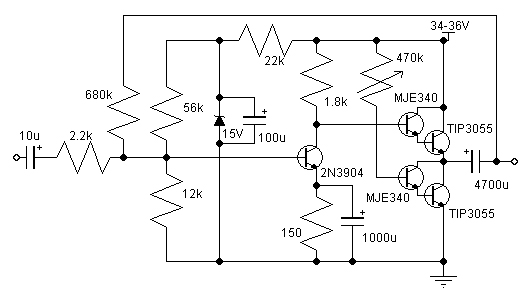
The 470K trim is to adjust the current-flow through the output transistor stack. This will act like a "near-constant current source", with darlington current gain (Hfe) of say ~(100 x 40 = 4,000).
Remember E = I R (volts = current times resistance)
And Ice = Hfe x Ib (current thru transistor = current gain times current-into-Base)
The 470K trimpot sees most of the power supply (36 - 1.4V of lower darlington cascade = 34.4 volts). Using I = E/R from above, = 34.5/470,000 = 0.0000734 amp. Multiplied by Hfe (4000, set) = 0.3 amps. Since each output transistor will see about half the dissipated power, then working with P = I E (power = current times volts), = 0.30 x 36 = 10 watts. Each output transistor sees about 5 watts.
Of course, that's at 470K setting, and making gross assumptions about gain for the lower darlington pair. In practice, one would adjust the 470K from its highest value downward, while measuring the current flow (with a small value, say 0.1 ohm/5% resistor in series with the upper darlington's collector, to V+ power supply.) (again, use E = IR, or I = E/R ... measure the voltage across the resistor with your digital multimeter, then knowing R, you get I. Likewise, recalling that the two output darlingtons must be on a heat sink, adjust them to be say, "25 watts" quiescent (no signal), and see how hot the heat sink gets after a few minutes. It should be "pretty hot, but not burning to touch".
In essence, the 470K + constant-current source arrangement allows the output impedance, and total power output to be adjusted. Its kind of a cute design, actually. But unfortunately, it will have source-sink nonlinearity. I guess that's what the nice 680K negative feedback resistor is for ... linearize the thing.
My prediction is - if you do the above - get a large heat sink, get an additional 0.1 ohm current-measurement resistor (and just solder it in, leave it in place), do the adjustments for heat ... this little circuit will provide remarkable amusement for awhile, on the cheap.
One PS: The 22K fixed resistor from power supply to 56K base pull-up resistor ought to be replaced with a 50K trimpot, as well. There will be quite a bit of as-delivered variation of the 2n3904 input transistors, so you may want to have this adjustable. The NET EFFECT of such adjustment will be the setting of the half-of-V+ operating point of the output Darlingtons. Nice to have.
I say "build it" and see how it goes. The parts certainly are cheap. You'll probably spend more on the chassis (and since you got to make two of them, one for each channel), and the power supply, than on the amplifier(s) themselves. Still ... contrary to the advice above to forget about it ... when the amplifier is as easy as this, its often worth doing ... just to say you did.
WARNING - WARNING - WARNING ... be very, very careful to ensure that the trimpot 470K is at "470K" before powering up. If it were "zero" (wiper at the other end of its range), then the output transistors will spectacularly blow up. Which... probably isn't what you would want. IF YOU WANT SAFETY ... then put the 470K trimpot in series with a 100K resistor ... which then gives a lower limit of 100K. While the output transistors might rapidly get hot, at least they won't turn into small nuclear reactors gone wild.
And 100K resistors are like what, 5 cents? Cheap protection.
GoatGuy
I am sure it will work - if you take care, as GoatGuy tells you.
The sound quality may not be the best.
The level 10-14 Watt Class A is a good choice. Not too much heatsinking.
If you are looking for 10 Watt Class A, then JLH Class A might be a better choice:
http://www.diyaudio.com/forums/solid-state/3075-jlh-10-watt-class-amplifier.html
The sound quality may not be the best.
The level 10-14 Watt Class A is a good choice. Not too much heatsinking.
If you are looking for 10 Watt Class A, then JLH Class A might be a better choice:
http://www.diyaudio.com/forums/solid-state/3075-jlh-10-watt-class-amplifier.html
The current biasing of the output stage with the 470K pot looks like an accident waiting to happen. Bearing in mind that current gain increases with temperature, I wouldn't be surprised to see thermal runaway with that circuit.
Also, what's with the 680K feedback resistor? The designer can't seriously be aiming for a voltage gain of 300.
Also, what's with the 680K feedback resistor? The designer can't seriously be aiming for a voltage gain of 300.
Death of Zen - A new Class-A power amp
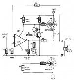
I prototyped this as a headphone amp and it is straightforward. It might be what you're looking for. It is certainly better than your original circuit.
I prototyped this as a headphone amp and it is straightforward. It might be what you're looking for. It is certainly better than your original circuit.
7-15, subtly different design.
Postscript - Its not drawn "right" but see that little diode in parallel with the 100 uF cap? That's actually a ZENER diode, rated at 15 volts. (if you look carefully you can see the wiggle in the cathode) Kind of a "poor man's regulator".
It would be much better to lose the 22K resistor entirely, and the zener, and replace both with a 3-terminal, 15 volt regulator, and a 1 uF capacitor to ground. Much better regulation, just about the same price, and definitely doing "what was intended". Then, I'd replace the 56K resistor with a 25K resistor and a 50K trimpot, so as to make the biasing of the first transistor variable.
Simple adjustment, really.
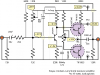
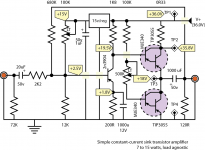
Here's my version... just for amusement. NOTE THAT THE VALUES of the emitter resistor on Q1 are different than the spec. And that I've put in the 'adjust to these values' settings as well.
GoatGuy
Attachments
Do you have the layout?Death of Zen - A new Class-A power amp
I prototyped this as a headphone amp and it is straightforward. It might be what you're looking for. It is certainly better than your original circuit.
Can I use MJ15003 to replace MJL21194?
- Status
- This old topic is closed. If you want to reopen this topic, contact a moderator using the "Report Post" button.
- Home
- Amplifiers
- Solid State
- About 10-14W Class A amplifier


