Hi All,
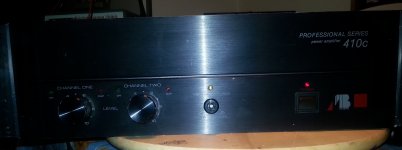
I just got a hold of one of these amps but it is not without some issues. Both channels function properly more or less, low DC offset, doesn't get hot while idling but it produces less power than specified, 200watts vs. 250 at 7 and a paltry 450 bridged.
The clip LEDs dont light up when amp is driven into that condition, signal presence LEDs seem fine though. They will illuminate dimly with load removed though..
The amp is in a permanent "on" state regardless of power switch position. I do believe there is a triac involved in the power-up circuit so I suspect a possible fault there.
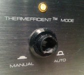
Whats most puzzling is a feature called "Thermefficient Mode" which can be engaged via the front panel switch. I have absolutely no idea of what that possibly could be. It appears that the switch cap has been broken off but it still engages and disengages but regardless what position it`s in, the accompanying yellow LED remains lit yet nothing happens to the output signal. It`s like the feature is permanently active, perhaps that would explain the limited output power, dunno.
Another mystery is there are 2 bridge rectifiers, is it possible that the Thermefficient mode switches between the two? There is one supplying B+ B- voltages come in at +62 -62 (124)respectively but the second bridge has a much higher DC voltage of 153vdc at its terminals.
There is little or no information available on this particular model except for some random scans that include bits and pieces of at least three model incarnations.
I just got a hold of one of these amps but it is not without some issues. Both channels function properly more or less, low DC offset, doesn't get hot while idling but it produces less power than specified, 200watts vs. 250 at 7 and a paltry 450 bridged.
The clip LEDs dont light up when amp is driven into that condition, signal presence LEDs seem fine though. They will illuminate dimly with load removed though..
The amp is in a permanent "on" state regardless of power switch position. I do believe there is a triac involved in the power-up circuit so I suspect a possible fault there.
Whats most puzzling is a feature called "Thermefficient Mode" which can be engaged via the front panel switch. I have absolutely no idea of what that possibly could be. It appears that the switch cap has been broken off but it still engages and disengages but regardless what position it`s in, the accompanying yellow LED remains lit yet nothing happens to the output signal. It`s like the feature is permanently active, perhaps that would explain the limited output power, dunno.
Another mystery is there are 2 bridge rectifiers, is it possible that the Thermefficient mode switches between the two? There is one supplying B+ B- voltages come in at +62 -62 (124)respectively but the second bridge has a much higher DC voltage of 153vdc at its terminals.
There is little or no information available on this particular model except for some random scans that include bits and pieces of at least three model incarnations.
Attachments
The mains transformer has additional higher voltage tapping's that can be selected using the second bridge to boost the main rails. That is all the Thermefficient mode appears to be.
> 200watts vs. 250 at 7
> B+ B- voltages come in at +62 -62
> second bridge has a much higher DC voltage of 153vdc
I will assume "7" should be 8 and 153 is +/-76V.
200W @ 8r is 56.6V peak. 5V shy of an observed 62V.
250W @ 8r is 63.2V peak.
Assuming the actual clipping power should be 300W (so a 250V spec will usually be valid):
300W @ 8r is 69.3V peak. 6V shy of an observed 76V.
Yes, you are stuck in "lower power" mode.
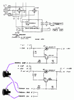
This is mostly on "Switchdown PCB", page 23. See attached snip-job.
The main page shows one thermal gizmo to Switchdown; the Switchdown page shows two apparently in series. (Ah-- one is really the manual "efficient" switch. Check that.)
From the implied logic, if the thermal gizmos (and switch) are short, the transistors turn-on the SCRs and use power from the higher PT taps. Therefore the thermal gizmos are NC, and go Open when things get hot.
The first diagnostic is to on a lamp limiter short Switchdown PCB terminal 4 to 7. This "tells" it to go high-power. Observe if the rails go up.
If they do not go up, you can poke the transistors, but my bet is the SCRs have failed. Strapping HV to LV on each side will short-out the SCRs and force hi-voltage mode (or smoke).
Failed HV rectifier (followed by failed SCRs) is another possibility.
With great luck, you only have a failed thermal gizmo (or manual switch).
With great bravery, you could just jumper to hi-volt mode permanently. This all seems like an over complication. And somebody thought the A and B versions did not need it. You may find out *why* they came up with this scheme for the C version. Or it may be that thermal cut-back was needed only to pass the FTC test and not for normal speech/music uses.
> B+ B- voltages come in at +62 -62
> second bridge has a much higher DC voltage of 153vdc
I will assume "7" should be 8 and 153 is +/-76V.
200W @ 8r is 56.6V peak. 5V shy of an observed 62V.
250W @ 8r is 63.2V peak.
Assuming the actual clipping power should be 300W (so a 250V spec will usually be valid):
300W @ 8r is 69.3V peak. 6V shy of an observed 76V.
Yes, you are stuck in "lower power" mode.
This is mostly on "Switchdown PCB", page 23. See attached snip-job.
The main page shows one thermal gizmo to Switchdown; the Switchdown page shows two apparently in series. (Ah-- one is really the manual "efficient" switch. Check that.)
From the implied logic, if the thermal gizmos (and switch) are short, the transistors turn-on the SCRs and use power from the higher PT taps. Therefore the thermal gizmos are NC, and go Open when things get hot.
The first diagnostic is to on a lamp limiter short Switchdown PCB terminal 4 to 7. This "tells" it to go high-power. Observe if the rails go up.
If they do not go up, you can poke the transistors, but my bet is the SCRs have failed. Strapping HV to LV on each side will short-out the SCRs and force hi-voltage mode (or smoke).
Failed HV rectifier (followed by failed SCRs) is another possibility.
With great luck, you only have a failed thermal gizmo (or manual switch).
With great bravery, you could just jumper to hi-volt mode permanently. This all seems like an over complication. And somebody thought the A and B versions did not need it. You may find out *why* they came up with this scheme for the C version. Or it may be that thermal cut-back was needed only to pass the FTC test and not for normal speech/music uses.
Attachments
Last edited:
UPDATE
Major progress today, thanks for chiming in guys.
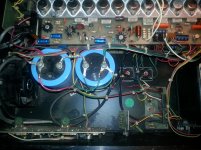
I tested the Thermefficient switch and it checked out good, I also replaced the 2 Triacs in the switchdown board, no change 🙁
The taped off orange wire beside the switching board didnt seem right and after inspecting the switching board, sure enough there was an unused point whose purpose now became obvious. I fired it up on the bulb tester as a precaution and the Thermefficient light went out, Bingo! B+ went up from 68v to 96v.
That translated to 457wpc 1khz @ clipping, both channels driven into 3 ohm loads, thats more like it. As an added bonus, the clip lights began illuminating properly albeit a little prematurely.
The amp now turns off and on as it should, triac tested good but the switch itself was wired backwards.
I didnt mention the fan issue in my original post but it too has been resolved. It ran so obnoxiously loud that I just disconnected it while troubleshooting the amp. Not only were the bearings shot but it was wired to the high voltage bridge running at >132vac.. A new fan wired to the low voltage bridge took care of that problem.
This amp was obviously "serviced" before as evidenced buy all of these modifications, God only knows why. The #3 output transistor was changed at one point but that hasnt given me any grief yet.
I would call this case closed 🙂
Major progress today, thanks for chiming in guys.
I tested the Thermefficient switch and it checked out good, I also replaced the 2 Triacs in the switchdown board, no change 🙁
The taped off orange wire beside the switching board didnt seem right and after inspecting the switching board, sure enough there was an unused point whose purpose now became obvious. I fired it up on the bulb tester as a precaution and the Thermefficient light went out, Bingo! B+ went up from 68v to 96v.
That translated to 457wpc 1khz @ clipping, both channels driven into 3 ohm loads, thats more like it. As an added bonus, the clip lights began illuminating properly albeit a little prematurely.
The amp now turns off and on as it should, triac tested good but the switch itself was wired backwards.
I didnt mention the fan issue in my original post but it too has been resolved. It ran so obnoxiously loud that I just disconnected it while troubleshooting the amp. Not only were the bearings shot but it was wired to the high voltage bridge running at >132vac.. A new fan wired to the low voltage bridge took care of that problem.
This amp was obviously "serviced" before as evidenced buy all of these modifications, God only knows why. The #3 output transistor was changed at one point but that hasnt given me any grief yet.
I would call this case closed 🙂
 Stuff that has been 'got at' by persons unknown is often problematic to sort out.
- Status
- Not open for further replies.