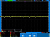
I made PCB for this amplifier.It works.When it is on regulated PSU it works absolutely perfect.When i put it on regular PSU i have 100Hz square wave on output ?????  .... all transistors r cold on idle.I tried 1000 things and cant figure out how to kill that self oscilation.I am using 2x60V DC with 10000uF x2 caps.Amplifier has amazing quality and output power.On regulated PSU without any input signal it is dead silent.But on regular PSU i can hear 100Hz from it ..... O M G .....its a square wave with 95% duty cycle.If i put 30R resistor before caps on + end it is quiet (maybe this can give u some idea which i missed 🙂 ).Amplitude of square wave is about 100mV peak to peak.Please help if u know how to stop this.Thank you all in advance.
.... all transistors r cold on idle.I tried 1000 things and cant figure out how to kill that self oscilation.I am using 2x60V DC with 10000uF x2 caps.Amplifier has amazing quality and output power.On regulated PSU without any input signal it is dead silent.But on regular PSU i can hear 100Hz from it ..... O M G .....its a square wave with 95% duty cycle.If i put 30R resistor before caps on + end it is quiet (maybe this can give u some idea which i missed 🙂 ).Amplitude of square wave is about 100mV peak to peak.Please help if u know how to stop this.Thank you all in advance.Attachments
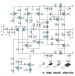
I made PCB for this amplifier.It works.When it is on regulated PSU it works absolutely perfect.When i put it on regular PSU i have 100Hz square wave on output ?????
Could be a form of motorboating - low frequency instability. If you increase the rail capacitance for the driver considerably (at least a factor of 10),
or remove the diodes, it may go away. Otherwise it might be some form of 120Hz ground loop noise.
Last edited:
Just a bad internet design. Too many things wrong to describe.
Why don't people just come to the forum for amp designs ?
You could increase those input stage decoupling caps but they are
running that VAS (Q5-8) real "hot" to drive the gate capacitances of the
mosfets.
EF (emitter follower) drivers would solve (below)the issue. This is how it is
done on amps that have to live up to the warranty(OEM).
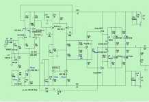
PS - amp below is the same type amp ...
but from this forum - not the internet ! (I have your schema -did not build it)
OS
Why don't people just come to the forum for amp designs ?
You could increase those input stage decoupling caps but they are
running that VAS (Q5-8) real "hot" to drive the gate capacitances of the
mosfets.
EF (emitter follower) drivers would solve (below)the issue. This is how it is
done on amps that have to live up to the warranty(OEM).
PS - amp below is the same type amp ...
but from this forum - not the internet ! (I have your schema -did not build it)
OS
Attachments
Actually, no.Just a bad internet design.
Its a copyrighted design from Silicon Chip magazine - 2001. The Logo, C and date tell you. It shouldn't even be posted on DIYAudio but since it does work and because quite a few people built it without problems, it's worth a reply.
Whether it is up to our present day, simulated, PPB THD design standards or any particular group of DIY current audio expectations, I don't really know. 😉
@dug
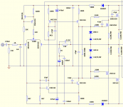
....I did try with cap frpm Q2 base to a +65V before i wrote here ..... that is not working.This is schematic of my design exactly as it is done.I did tests till early morning hours today ..... I tested all what one engeneer can test.
@rayma
.... It looks like that u r very close to a solution.I tested with osciloscope Q7 and Q8 ..... on both bases (common trace in this case) and on both emitors i have flat DC.But on driving side on colector of Q8 i have square wave.....Same thing on lower side.It looks like that only output stage is making troubles.And it looks like that diodes r doing this.I will try to increase zener voltages first and then i will try to remove them if that is not working.I will back with results soon as i do that."If you increase the rail capacitance for the driver considerably" - did u mean here to put cap from gate to source of output transistor?
....I did try with cap frpm Q2 base to a +65V before i wrote here ..... that is not working.This is schematic of my design exactly as it is done.I did tests till early morning hours today
..... I tested all what one engeneer can test.@rayma
.... It looks like that u r very close to a solution.I tested with osciloscope Q7 and Q8 ..... on both bases (common trace in this case) and on both emitors i have flat DC.But on driving side on colector of Q8 i have square wave.....Same thing on lower side.It looks like that only output stage is making troubles.And it looks like that diodes r doing this.I will try to increase zener voltages first and then i will try to remove them if that is not working.I will back with results soon as i do that."If you increase the rail capacitance for the driver considerably" - did u mean here to put cap from gate to source of output transistor?
Attachments
Are you saying that in effect, you increased R23 from 100R to 130R?......If i put 30R resistor before caps on + end it is quiet.....
Frome bridge rectifier i have +60V .... before main caps and that end if i put 30ohm resistor i dont have noise that i can hear.I tried new PSU to make sure that PSU is not a problem and it is the same.....Something is the problem with the design and i cant figure out what.100Hz which i have is synchronized with grid frequency.....Something is to sensitive and super small variation from PSU is amplified on output.....I dont have any idea from here what to do.I will not give up.
What does the overload indicator during the test? It has no current limiter for the LED.
Its wrong on sch...totaly about it.....ignore it.I fixed it but cant discuss now untill i fix this problem with amplifier.After that i will explain what and how to do.
Several years ago I built a similar circuit. At that time published in the Elektor. As I recall, I had exactly the same problem. That's what I found out points to the overload circuit.
Remove R25 and see if it then still oscillates.
Remove R25 and see if it then still oscillates.
@moschfet
I did remove it .... and i cut out complete that part.Same thing.I did tests with two bulbs on each rail of PSU voltages.From "minus" of bridge rectifier to a bulb and then to a caps and amplifier.....same for positive.There is no noise that i can hear ..... but i can see 100Hz on 50mV on scope.If i short "minus" bulb its quiet and no problems....but if i short "plus" bulb i have oscilating.....So problem is between positive rail and ground.I tried to move ground path and i made also various changes in resistor values etc. ..... still no solution.I have this oscilating and amp has full power output easy....it works stable.....no over heating......no high frequency self oscilating....BUT i have 100Hz.Somehow super small AC rail on DC rails is amplified and it is present on output.I puted a cap from the colector of Q2 to ground to eliminate all noise.Zero effect.
I did remove it .... and i cut out complete that part.Same thing.I did tests with two bulbs on each rail of PSU voltages.From "minus" of bridge rectifier to a bulb and then to a caps and amplifier.....same for positive.There is no noise that i can hear ..... but i can see 100Hz on 50mV on scope.If i short "minus" bulb its quiet and no problems....but if i short "plus" bulb i have oscilating.....So problem is between positive rail and ground.I tried to move ground path and i made also various changes in resistor values etc. ..... still no solution.I have this oscilating and amp has full power output easy....it works stable.....no over heating......no high frequency self oscilating....BUT i have 100Hz.Somehow super small AC rail on DC rails is amplified and it is present on output.I puted a cap from the colector of Q2 to ground to eliminate all noise.Zero effect.
If i test with scope all voltages on transistors.....all are flat DC.Only on gates i have square wave modulated on DC biasing voltage.....and from there i have it on output.
🙁 OK!
Then back for observation. 😎
What kind of resistance are R23,24? If the heavy inductive thereby an RLC resonant circuit could occur.
Then back for observation. 😎
What kind of resistance are R23,24? If the heavy inductive thereby an RLC resonant circuit could occur.
There is also grounding of the supply bypass caps. No doubt you are aware of the issue but if you don't have the original PCB layout, perhaps you missed it here. C13,14,15,16 etc, should all return via separate traces to star power ground - not signal ground. Neglecting this usually results in low level rectifier noise.
I made it.So it was NOT about the schematic and the design but about the ground.
@Ian Finch .... Yes,thats exactly what i did and it start working with flat output.
Thank you all.
@Ian Finch .... Yes,thats exactly what i did and it start working with flat output.
Thank you all.
That's great, 'hope you can now enjoy the results. It is pleasing for me too, knowing that I am not alone when I also make that mistake.
 ..... Results r really good.About cliping indicator.....its power supply should be 12V to 15V and 680R resistor need to be placed in serial connection with LED.This amplifier works like a charm.First what i will do in next month i will develop switching PSU for it.Now i am using huge toroid and it works really good.
- Status
- Not open for further replies.
- Home
- Amplifiers
- Solid State
- AB Mosfet strange behavior