There is no good and cheap DIY product. It will cost more than commercially available products. Mine will cost me several thousand Euros but I don't calculate when pleasure is the reward. All these tools, measurement equipment, aluminium plates, table saw, router, drills, all these boards that I have assembled and just discarded. It costs a lot.
This is the way the life is, it costs, but I've made some courageous decisions in my life, so I dont have to care or regret. I simply don't care at all. Its fun and that counts.
This is the way the life is, it costs, but I've made some courageous decisions in my life, so I dont have to care or regret. I simply don't care at all. Its fun and that counts.
I think you have a faulty potentiometer in your preamplifier.I already wrote that the sound in acoustics sounds excessively loud at the beginning of volume control. Can someone suggest how to make it quieter by changing only the power amplifier circuit?
Alas, no, I even changed it to a similar one. I think it's about the circuitry from the Chinese.
Berlusconi, are you from Italy?
Berlusconi, are you from Italy?
Remember, you had R21 resistor with 22R value instead of 100K. This must be some systemic error because it appears on the both channels. My moto is: if you want to know how many teeth a donkey has, go to the stable, open donkeys' mouth and count. Some people might open The Holly Scripture to find the truth, but the truth is in a donkeys' mouth.Alas, no, I even changed it to a similar one. I think it's about the circuitry from the Chinese.
Berlusconi, are you from Italy?
You can easily verify values of every resistor on your boards. Other components too.
PS: An alternative is to put some known voltage at the input, 1VAC 50Hz, for example, and measure the output as VRMS with your multimeter. Then you can calculate amplification factor. You may do that with different voltages at the input.
Last edited:
I noticed an even increased heating of the A1145 / A2705 transistors and the 2240/970 pair. Don't you have this effect on your boards?
Of course, up to 60 C.I noticed an even increased heating of the A1145 / A2705 transistors and the 2240/970 pair. Don't you have this effect on your boards?
Hi Berlusconi. According to my measurements, the input voltage gain has a value of about 30. Have you measured yours?
I have the same value. Your problem is elsewhere, your A60 is OK.
Is your potentiometer linear or logarithmic? ... or even "right hand logarithmic" taper.
Is your potentiometer linear or logarithmic? ... or even "right hand logarithmic" taper.
Last edited:
Aliexpress, again. Obviously, this isn't the problem I can help you fix.
Try to solve your problems yourself otherwise it is pointless to Do-It-Yourself.
Seek the culprit elsewhere - according to amplification factor the amplifier functions properly, If you have 10mVRMS at the input you will have 300mVRMS at the output, if you have 0mVRMS there will be just few mVRMS at the output, etc, etc.
Something else causes your problems.


Hello everyone to the new 2022.
While browsing the internet, I noticed that you are moving the thread of the Chinese clone Accuphase A60 ++ amplifier. I have the V 1.1 versions of the tiles. similar to colleague "vmk2002".
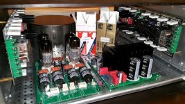
In my case, the topic has been dragging on for several years (due to the lack of time) and it will be something similar, but based on an additional version of the preamplifier, i.e. a 2 in 1 hybrid (amplifier + preamplifier "PANA-MERA" - HYBRID POWER AMPLIFIER / PREAMP TUBE NOS , CLASS A / AB).
In the near future, it will be equipped with additional components and functional functions. You will see for yourself as soon as I motivate myself to act (these are my plans for this year 2022).
The potentiometer will definitely be different than that of my colleague "vmk2002". It will get really tight inside the housing.
As for the capacitors used, I gave up Chinese products in favor of Rubycon 8pcs x 10000uF / 63v, diameter 30mm (made in japan) due to the quality and limitations in the DISSIPANTE 4U - 1NPD04400N metal housing.
I could use Mundorf M-Lytic AG MLGO 10000 uF 63V capacitors, 30mm diameter, made by the German producer FTCAP Fischer und Tausche Capacitors - FTCAP GmbH, but I decided to spend the savings on capacitors on parts for my new DAC.
Below is a photo of partial assembly works.
greetings
Thomas_XLR
While browsing the internet, I noticed that you are moving the thread of the Chinese clone Accuphase A60 ++ amplifier. I have the V 1.1 versions of the tiles. similar to colleague "vmk2002".
In my case, the topic has been dragging on for several years (due to the lack of time) and it will be something similar, but based on an additional version of the preamplifier, i.e. a 2 in 1 hybrid (amplifier + preamplifier "PANA-MERA" - HYBRID POWER AMPLIFIER / PREAMP TUBE NOS , CLASS A / AB).
In the near future, it will be equipped with additional components and functional functions. You will see for yourself as soon as I motivate myself to act (these are my plans for this year 2022).
The potentiometer will definitely be different than that of my colleague "vmk2002". It will get really tight inside the housing.
As for the capacitors used, I gave up Chinese products in favor of Rubycon 8pcs x 10000uF / 63v, diameter 30mm (made in japan) due to the quality and limitations in the DISSIPANTE 4U - 1NPD04400N metal housing.
I could use Mundorf M-Lytic AG MLGO 10000 uF 63V capacitors, 30mm diameter, made by the German producer FTCAP Fischer und Tausche Capacitors - FTCAP GmbH, but I decided to spend the savings on capacitors on parts for my new DAC.
Below is a photo of partial assembly works.
greetings
Thomas_XLR
Attachments
Very beautiful! And it takes me two months to combine all these components. I always want to do better. Layout and connection is still a job. Sorry if something goes wrong, new year, spirits
Hello everyone! I took advantage of the long weekend and completed my power amplifier. At the same time, he took advantage of new knowledge:
1. It is necessary to phase the power supply of the transformers. In simple terms, all transformers are first connected to the network with unconnected wires of the secondary windings. The voltage indicator (indicator screwdriver) should not light up when phase L is correctly applied to the primary winding. Thanks to Prophetmaster.

2. Perhaps I have problem boards, but most likely this is a curve layout of the boards from the Chinese. It was expressed by noise in the high-frequency speaker and low-frequency speaker (obviously noise due to unstabilized power supply - 50 Hz). The soldered wire from IN GND to OUT GND helped. Moreover, it is important that it must have only 2 soldering points - at the ends! I tried 3 points (one of the tries on the GND capacitor of the power supply), the desired effect was gone.

1. It is necessary to phase the power supply of the transformers. In simple terms, all transformers are first connected to the network with unconnected wires of the secondary windings. The voltage indicator (indicator screwdriver) should not light up when phase L is correctly applied to the primary winding. Thanks to Prophetmaster.
2. Perhaps I have problem boards, but most likely this is a curve layout of the boards from the Chinese. It was expressed by noise in the high-frequency speaker and low-frequency speaker (obviously noise due to unstabilized power supply - 50 Hz). The soldered wire from IN GND to OUT GND helped. Moreover, it is important that it must have only 2 soldering points - at the ends! I tried 3 points (one of the tries on the GND capacitor of the power supply), the desired effect was gone.
Attachments
By the way .
In addition to this amplifier, the design of the DAC is created equally to the set, also in the hybrid version, the discrete op-amp / tube nose Philips PCC88, using the pcm1794 converter.
Below is a designed front panel for the DAC, everything is described "PANA-MERA - HYBRID DAC "
In addition to this amplifier, the design of the DAC is created equally to the set, also in the hybrid version, the discrete op-amp / tube nose Philips PCC88, using the pcm1794 converter.
Below is a designed front panel for the DAC, everything is described "PANA-MERA - HYBRID DAC "
Attachments

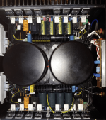
3. We managed to fit an additional 2x22000μF into each channel in a standard case. I connected each capacitor through a 1 Ohm 5Wt resistor. Their dimensions are 35x70mm .


The photo shows a two-story structure: soft start boards, indicator control boards, a power supply for the indicator board are on the first floor, under the transformers. Additional condensers have been added to the first floor.

In total, the view inside took on the following:

In total, the view inside took on the following:
Attachments
First vmk2002
Привет! (Russian: Hello)
Thanks for presenting your findings. I do indeed appreciate your substantial progres; you've started from someone who needed help for the most trivial things and now, you may share your knowledge with us. That's quite remarkable. Chape. You are finishing a great amplifier.
Thomas:
Cześć (Polish: Hello)
Welcome to the club.
I've read your Polish thread with the help of Google Translate. You have presented great photos and schematics. You have a great deal to show and I'm looking forward to share experiences with you. Keep working hard, it will pay-of, with great sounding amplifier. My configuration is: DAC-Preamplifier-Amplifier. This configuration may extract the maximum sound quality.
Slavko:
Zdravo! (Slovenian: Hello)
Just keep working hard.
Right now I am finishing the third DIY chasis for my three A60+ amplifiers. I plan to create three-way system comprising of six chanels. Building a chasis from the stratch is indeed challenging metal work if you want to do it right but I have good tools and sometimes I'm running out of time because I have many other obligations. I plan to finish everything this spring.
Meanwhile I plan to publish comprehensive measurements and comparisons of different transistors.
Happy new year to everyone
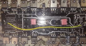
Hello to all! I compared my circuit and the circuit according to the link from the respected thomas XLR and noticed a significant difference in my opinion. This is the resistor outlined in red (picture below):

The value of this resistor is in fact 22 Ohm, and 33 Ohm is signed on the board. I unsoldered it, and noticed that the gain of the power amplifier dropped (it became equal to 1). I wondered if it was possible to select it in such a way as to obtain a gain that would result in a minimum of distortion and less noise in the absence of a signal (note that it is practically impossible to hear noise in the absence of this resistor, even if we put our ear close to the speaker membrane). Why don't the Chinese depict this resistor in the diagrams?

The value of this resistor is in fact 22 Ohm, and 33 Ohm is signed on the board. I unsoldered it, and noticed that the gain of the power amplifier dropped (it became equal to 1). I wondered if it was possible to select it in such a way as to obtain a gain that would result in a minimum of distortion and less noise in the absence of a signal (note that it is practically impossible to hear noise in the absence of this resistor, even if we put our ear close to the speaker membrane). Why don't the Chinese depict this resistor in the diagrams?
- Home
- Amplifiers
- Solid State
- A60(+) Amplifier. Build this?