First thought when I woke up this morning was "What was that about yesterday? . . . . Dog chase tail? . . . . . Bull charge red cape? . . . . . brain fart?. . . . . . ."
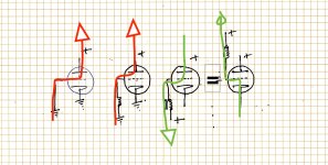
So I took a few minutes over coffee to figure out where I was getting tripped up and realized it was mostly rooted in a graphics problem. I more or less absorbed the way of looking at things on paper with plus volts at top of page and ground , 0V or minus V at bottom . The two with green arrows (electron current) show the error I wasn't recognizing.
All this came to a head playing with the so called "dynamic coupling" circuit. All the stuff I've seen online about it doesn't explain it very well so I still don't get how it can work unless the driver curve for GM and output tube GM curve are matched. Nothing about that in any of the writeups I saw.
Frank Blöhbaum's MTA article mentions high GM as a desireable quality for the driver in his dynamic coupled 811A revision of a friend's circuit but nothing about matching. I still don't know how it can possibly work without having the two tubes fighting or limiting each other in some way.
Anyway, thanks very much for making the grid current part clear. You've given me a perspective that's actually useful !
Attachments

I think he's trying to depict reverse grid current (gas and surface leakage) which can indeed be from anode to grid.
I have successfully converted a couple 6BQ6GT sweep tubes into lumps of useless glass when the screen grid got hot enough to emit electrons which immediately travelled to the plate this led to a red screen runaway and a tube arc. The cathode was not involved once the screen grid got real hot. Autopsy revealed a nice well formed cathode and a pair of naked screen grid rods. On the second attempt I killed the heater supply once the fun began with the same results. The results of these experiments revealed the weak link in screen driven sweep tubes and marked the end of my year long fascination with screen drive. I then experimented with dual (G1 and G2) drive before discovering UNSET.
I did not try it but I would expect similar results from slamming a triode hard into A2 with near square waves for an extended period of time. During this condition there will be times when the plate voltage is low (saturation) while the grid voltage is high. If the driver can source a lot of grid current (mosfet follower) the grid can be over dissipated. I was considering the small group of idiots like myself who are going to plug a guitar preamp into every amp I make, even a 300B SE.
I did not try it but I would expect similar results from slamming a triode hard into A2 with near square waves for an extended period of time. During this condition there will be times when the plate voltage is low (saturation) while the grid voltage is high. If the driver can source a lot of grid current (mosfet follower) the grid can be over dissipated. I was considering the small group of idiots like myself who are going to plug a guitar preamp into every amp I make, even a 300B SE.
Why does the bypass cap fail / explode in that case?. . . . . . one of the cathode resistors went open and the associated bypass cap exploded.
There are many online references to it happening but I didn't see any description of the process in terms of electronics. (Mostly guitar players asking what they should do about it.)
Yes, red is reverse grid current , green is forward . I hope I have them correctly. (Arrows pointing in electron flow direction. )I think he's trying to depict reverse grid current (gas and surface leakage) which can indeed be from anode to grid.
My assumption is that in the end , whatever element in the tube the current appears to be coming from, it has to be sourced from the power supply so the line showing current flow will always go to ground , whether inside the tube through cathode or or outside through whatever pathway is there.
You mean the one below? A few 811 types in the drawer, I was thinking I'd try a channel of it on the way to one of the Blöhbaum circuit . Thanks for talking about your experience. I won't waste the time on it.Many years ago there was a popular schematic circulating around the web that used a triode wired 6V6 driving the grid of an 811A in a manner similar to your dynamic coupled 2 circuit. It worked pretty well at low power output but got pretty ugly sounding if driven anywhere near clipping. I gave up on it after some tinkering, and eventually traded my 811A's to a ham radio operator.
I still wish someone would say something about that dynamic coupling circuit per se. If the two tubes don't have identical curves for Vk/Ik on the driver and Vg/Ig on the output tube how can it work without the two tubes getting in each other's way ?
Thanks
Attachments
Your diagram is still a little confused. Try this (conventional current flow):Yes, red is reverse grid current , green is forward . I hope I have them correctly. (Arrows pointing in electron flow direction. )
My assumption is that in the end , whatever element in the tube the current appears to be coming from, it has to be sourced from the power supply so the line showing current flow will always go to ground , whether inside the tube through cathode or or outside through whatever pathway is there.
There is an invisible diode between the grid and cathode of every tube, so the driver tube is effectively feeding a diode to ground. Does that help?how can it work without the two tubes getting in each other's way ?
Imagine if you connected a 35V capacitor, with a resistor in series, directly across a 400V supply. Probably bang! That's basically what you have when the cathode resistor goes open (the tube is the series resistor).Why does the bypass cap fail / explode in that case?
Last edited:
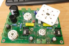
I was using an SSE board for this test. Back in my pre-teen years I discovered that the 6BQ6 and 6DQ6 types have a pinout that is compatible with the typical audio output tubes if you wire the plate cap to pin 3 of the tube socket. Many of my DIY guitar amps in the early 60's used a Fender Champ circuit with a 6BQ6GT for the output tube. I never could understand why that worked but the larger 6DQ6 tubes just red plated and made the transformers hot. It would be some time before I learned about things like bias, load lines and impedance.Why does the bypass cap fail / explode in that case?
There are many online references to it happening but I didn't see any description of the process in terms of electronics. (Mostly guitar players asking what they should do about it.)
Once a tube reaches the point where the ionized contaminants in the vacuum reach the plasma stage the tube is no longer behaving anything like a controlled electron device. It is a low impedance between any two electrodes in either direction. The impedance is mostly dependent on the "gas" temperature and pressure. Most of my experiments are done with bench power supplies. I looked at all of the other pictures from this experiment but none reveal which power supply I was using, but it was likely my Fluke 407D which is rated for 300 mA and can easily put 400 mA through something like a superheated vacuum tube, probably more. 400 to 500 mA through a 560 ohm cathode resistor will drop over 200 volts across it making life rather tough on a 63 volt bypass cap across it. One, or both will die. I still have that "test" SSE board as it was the first one made. it currently has 100 volt bypass caps across the cathode resistors.
Many of the current new production audio tubes are built with a less than stellar vacuum and purity level of the internal components. Old tubes used to just loose emission and die. Much of the new production stuff dies by red plate runaway in the output tube socket. Many vintage guitar amps ran the tubes at or above the published specs. They were made when line voltages were about 115 volts or less. Now I get from 123 to 127 volts depending on the use of heat or AC. Old stuff runs hot on today's line power.
I have never really explored that circuit other than building that amp because I had the parts probably 20 to 25 years ago. This was during the time that I got over 100,000 well used vacuum tubes in exchange for a few weekends of work cleaning out a warehouse full of surplus that was in the process of being demolished for new housing construction. My main mission was to figure out what tubes to keep and what to sell, trade, or trash. I decided early on that the 811A's and 812's went into the sell / trade pile because I was more intrigued by the larger collection of 211A's and 845's.You mean the one below? A few 811 types in the drawer, I was thinking I'd try a channel of it on the way to one of the Blöhbaum circuit . Thanks for talking about your experience. I won't waste the time on it.
I still wish someone would say something about that dynamic coupling circuit per se. If the two tubes don't have identical curves for Vk/Ik on the driver and Vg/Ig on the output tube how can it work without the two tubes getting in each other's way ?
To further confound the results of that test I would make another discovery later on. I had purchased a new sealed bulk pack box of 100 NOS Sylvania 6V6GT's at an auction at a NASA storage facility in Florida probably in the late 90's. I took the sealed box home and put it in the closet where it sat for probably a year or more before I decided to make some 6V6GT based guitar amps. I was surprised to find several tubes in the box with white, cloudy, or no getter. This box had been kept in a climate controlled storage facility so they should have been perfect. I rigged up a test amp to try out some of these tubes. Many were gassy, some went into red plate meltdown as soon as power was applied. I tested all 100 tubes and tossed over HALF of them. There was obviously some severe contamination issue when these tubes were made. The rest of the tubes were tested for THD at max spec and the good ones went back into the box in the closet of an air conditioned house in Florida.
During the development of the SSE, I got out the box of 6V6GT's and to my surprise, more of them had gone gassy while sleeping on the shelf. I set up an SSE to run the 6V6GT's at max spec and weeded out 7 more bad tubes. Unfortunately these were the tubes that were likely used when I built that 6V6 into 811A test amp so the test results may have been invalid. Now 20+ years later only a dozen or so of that box of 100 tubes remain useful and I have never trusted than in anything that will see much use. The few good ones do seem to work OK but they probably wouldn't last long if run hard.
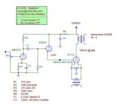
As stated by Merlin the driver tube is essentially a cathode follower working into a diode. The current through that diode is modifiable by the plate voltage in a relationship approximated by 1/Mu. Steve Bench called this behavior "inverted triode" mode and even made some audio amps using 6AS7's and the like with drive applied to the plate and output taken from the grid. Google finds some of his old web stuff on inverted triode mode.
I never explored the dynamic coupling or inverted triode mode, but I always suspected that the 6V6 -> 811A amp could be improved by forcing more current through the 6V6GT with a resistor or CCS to a negative supply so that it ran at a more constant current which would keep it's Gm from varying all over the place. Maybe the high Mu of the 811A offered enough immunity from the varying plate voltage to minimize this effect, but I didn't look too far into it before wandering down the 211A / 845 amp path.
I started down that journey with a schematic called the poor man's Ongaku. Didn't like that one either but it eventually morphed into a three stage TSE, which I just sold for parts at the Dayton Hamfest.
Attachments
Yes, you are right ! I repeated my mistake, again bulldozing ahead with images. This is what I thought I was drawing to show where I got mixed up.Your diagram is still a little confused. Try this (conventional current flow):
There is an invisible diode between the grid and cathode of every tube, so the driver tube is effectively feeding a diode to ground. Does that help?
Please bear with me here. The wording is the clearest I can make it.
What I have trouble with is V/I discrepancy between the two tubes. The data sheets clearly show given current at specified positive grid voltages.
The way I think of it: When the driver acts to swing the output grid to a given voltage, in order for the output tube grid to be at that voltage , the grid current commensurate with being at that voltage must flow. If the driver tube's characteristics are such that it wants to conduct less current (or more) at that voltage then there will be a conflict resulting in the discrepancy distorting the ideal waveform.
At the extreme, if the output tube's grid swings negative, according to the data sheet grid current will stop flowing , cutting off the driver.
This is what I think about, yet there are reports of successful builds, so I question it.
Ahh, the same voltage that makes some worry about cathode stripping. I see that now. ThanksImagine if you connected a 35V capacitor, with a resistor in series, directly across a 400V supply. Probably bang! That's basically what you have when the cathode resistor goes open (the tube is the series resistor).
So the capacitor is well on its way out by the time the resistor opens. That's the detail that makes the picture clear. Otherwise bypass caps would be popping every time a typical tube amp circuit was powered on.but it was likely my Fluke 407D which is rated for 300 mA and can easily put 400 mA through something like a superheated vacuum tube, probably more. 400 to 500 mA through a 560 ohm cathode resistor will drop over 200 volts across it making life rather tough on a 63 volt bypass cap across it. One, or both will die. I still have that "test" SSE board as it was the first one made. it currently has 100 volt bypass caps across the cathode resistors.
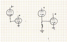
I put the choke loaded cathode follower circuit in the post #21 sketch above as I first ran across it being used as a Dynamic Coupling modification to allow swing both sides of Vg=0. I guess that's sort of a passive version of what you are talking about. (?). . . . . . . . but I always suspected that the 6V6 -> 811A amp could be improved by forcing more current through the 6V6GT with a resistor or CCS to a negative supply so that it ran at a more constant current which would keep it's Gm from varying all over the place. . . . . . . .
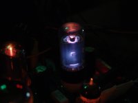
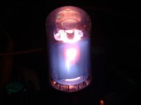
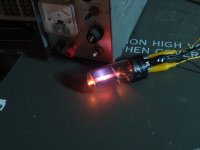
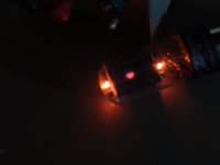
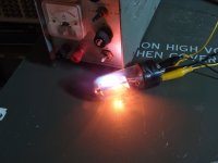
PS. The glow in that fourth pic you posted looks a lot like some interstellar nebula. cool.
Attachments
PS. The glow in that fourth pic you posted looks a lot like some interstellar nebula. cool.
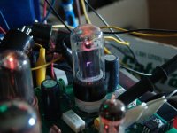
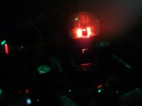
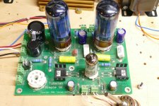
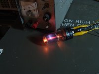
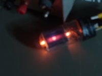
That one started sparking out shortly after that picture was taken so the power was killed. The bypass cap was likely already well on it's way to dead since this was the third tube I fried. Number 4 went until the cap exploded. The other channel had a good tube in it and it just kept on working. The tube that I pulled from the "test" channel is visible in the second picture of post #27 laying upside down on the board.
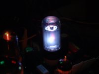
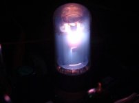
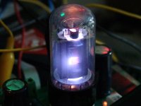
Here is Number 4 from power up to dead. The dead photo shows some glowing hot internals. The board is unpowered at this time. I hit the kill switch when the cap popped. The greenish glow is a reflection of the scope traces.
The dates on these pictures are May of 2006. That makes this one of the first ever SSE's which I later determined to be the first production board I ever built. Some time and far too many experiments later it went into the box of dead circuits. It's a pretty big box!
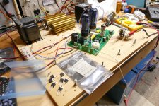
Recently I needed a board to test some alternatives to the IXYS 10M45S since they were unobtainable for much of last year. I dug into the box of dead boards and found this old SSE wearing rather large tube socket where I tried some 4D32's in SE. The giveaway was the 100 volt cathode bypass caps. The 17 year old board fired right up and worked fine despite its rather crusty looks. It's now back in the box of dead circuits.
That one started sparking out shortly after that picture was taken so the power was killed. The bypass cap was likely already well on it's way to dead since this was the third tube I fried. Number 4 went until the cap exploded. The other channel had a good tube in it and it just kept on working. The tube that I pulled from the "test" channel is visible in the second picture of post #27 laying upside down on the board.
Here is Number 4 from power up to dead. The dead photo shows some glowing hot internals. The board is unpowered at this time. I hit the kill switch when the cap popped. The greenish glow is a reflection of the scope traces.
The dates on these pictures are May of 2006. That makes this one of the first ever SSE's which I later determined to be the first production board I ever built. Some time and far too many experiments later it went into the box of dead circuits. It's a pretty big box!
Recently I needed a board to test some alternatives to the IXYS 10M45S since they were unobtainable for much of last year. I dug into the box of dead boards and found this old SSE wearing rather large tube socket where I tried some 4D32's in SE. The giveaway was the 100 volt cathode bypass caps. The 17 year old board fired right up and worked fine despite its rather crusty looks. It's now back in the box of dead circuits.
Attachments
I also own this boatanchor and still am quite amazed about this more than 60 years old gear, especially about it's precisely adjustable output voltage....but it was likely my Fluke 407D which is rated for 300 mA and can easily put 400 mA through something like a superheated vacuum tube, probably more.
Best regards!
I bought my 407D on Ebay 20+ years ago as "non functional scrap" for $25 plus $45 to ship it across the country. it worked fine when I got it and I opened it up once to tighten up the loose bias voltage pot. A few months ago it died, lost regulation and put out lots of hum so I dug into it. One of the Twist Lok can electrolytics was open so I soldered a cap across it and put it back together. I deduced a build date in the mid 1960's from the date codes on the parts. How much of todays electronics will still work in 60 years?
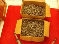
I opened up the box of NOS 6V6GT's that has remained closed for at least 10 years. I pulled out about a dozen that had the lowest THD when I was packing up to leave Florida and tossed the rest into a box. It looks like I have a few more that are ready for the blue light test. The 12 "good" ones have seen little use, mostly for testing ideas, so I don't know how well they work either.
I opened up the box of NOS 6V6GT's that has remained closed for at least 10 years. I pulled out about a dozen that had the lowest THD when I was packing up to leave Florida and tossed the rest into a box. It looks like I have a few more that are ready for the blue light test. The 12 "good" ones have seen little use, mostly for testing ideas, so I don't know how well they work either.
All the stuff that runs relatively cool and was designed within ratings, I suspect. Might need to top up EEPROMs and Flash every decade or two though.How much of todays electronics will still work in 60 years?
If only mechanical systems were as reliable - the number of DVD drives and digital cameras I've had to replace through mechanical failure...
Just an aside, but how critical is tube storage, and what is the enemy of a tube? I had not given this any thought until I read a similar comment as above on the UK vintage radio site. After some discussion it was decided that humidity leads to condensation and corrosion of the pins, and that can lead to a breach of the seal between pin and glass. In my case my storage room can end up being well below zero in winter, but my thought is dry air is the key element.I took the sealed box home and put it in the closet where it sat for probably a year or more before I decided to make some 6V6GT based guitar amps. I was surprised to find several tubes in the box with white, cloudy, or no getter. This box had been kept in a climate controlled storage facility so they should have been perfect.
The 6V6GT tubes I mentioned were stored under ideal conditions for their entire life in a controlled storage facility at the Kennedy Space Center in Florida. The only plausible explanation for what happened is that these tubes were contaminated or poorly sealed during manufacturing.Just an aside, but how critical is tube storage, and what is the enemy of a tube?
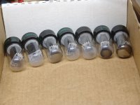
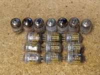
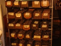
I got over 100,000 tubes for free back in the 1990's. They had been stored loosely in boxes, bags, and even 55 gallon drums in an abandoned warehouse in central Florida. Vandals, vagrants, and squatters had spent some time there generally trashing the place and breaking tubes by the thousands. It was here that I found dozens of broken 211's, 845's and 833A's. I got to learn about every possible variation of the 807 / 1625 tubes ever made without breaking one myself. The windows in the building had been broken out for decades and Pidgeon's had roosted there leaving a white sticky coating all over the place. I also learned that Pidgeon crap is highly corrosive to vacuum tube pins. Anything that looked like the tubes in the first picture and all of the broken stuff was discarded on site. The rest were transported to my home 200 miles away for sorting. The tubes I had too many of, or would never use were sold in bulk. Who needs over 100 pounds of 6AL5's?
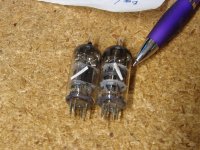
Do tube manufacturers make mistakes, or do assembly line workers get bored? Why would GE put a spare heater element inside a tube? What are the odds of finding two of them?
I set up three or four sorting racks like these along with a 55 gallon drum for trashing the ugly stuff that made it's way to my house.
It took nearly 5 years of weekends to sort them all. There were a few gems hidden inside the huge pile of rocks. This small collection along with about 50 good Raytheon 5842's led to the decision to use the 5842 in the design of the TSE amp. I simply tried every possible candidate tube that I had a few of in a breadboard with a 45 output stage until I came upon the CCS loaded, mosfet follower buffered "PowerDrive" circuit that is used in the TSE and TSE-II today. The 5842 consistently offered the lowest THD at enough output voltage to drive a 45 or 300B to full power.
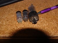
Some of the "rocks" got tested before disposal. This damper tube had a hole in its plate. It also worked fine, but who is going to trust it, so it met the power supply for an unhappy ending. The first picture was taken with heater power only to show the hole. Then I cranked up the plate current until the plate began to glow. Why stop there? Somewhere far beyond the spec limit the blue ray of death appeared. Way beyond the spec limit the blue turned to white. At the limit of my power supply things started to come out of the other side of the plate. At this point the test subject expired quietly.
I was wandering an outdoor flea market in Florida when I stumbled (literally) across an old Sparton radio chassis in the dirt. It had been left outside in Florida for several years and was quite rusty and packed with dried mud. A sticker on the chassis stated that all of the tubes had been replaced in 1929 and 5 or 6 National Union globe style tubes were in the chassis. I gave the vendor $5 for it and took it home. There I pulled the tubes and tossed the rest. The output tubes were a push pull pair of NX-483's which seemed to be like a 45 with a 5 volt filament. Those tubes are still in my original Lexan TSE today. They are now 94 years old and still working. Will they make it to 100? Apparently poor storage doesn't do too much damage to a well made tube.
Attachments
-
 DSC00080.JPG324.9 KB · Views: 55
 -
 DSC00076.JPG309.2 KB · Views: 51
 -
 DSC00070.JPG180.2 KB · Views: 61
 -
 DSC00068.JPG123.1 KB · Views: 53
 -
 DSC00042.JPG665.4 KB · Views: 54
 -
 DSC00052.JPG465.8 KB · Views: 54
 -
 DSC00046.JPG547.6 KB · Views: 52
 -
 DSC00033.JPG571.7 KB · Views: 54
 -
 DSC00054.JPG576.2 KB · Views: 52
 -
 DSC00089.JPG354.5 KB · Views: 56
Last edited:
You can fix the grid voltage and vary the cathode voltage as in the UNSET circuit, or you can fix the cathode voltage and vary the grid voltage as in many conventionally biased circuits. Here the mechanism providing the gain is the same, the voltage between the grid and cathode is changing. The grid current is not part of the gain mechanism, it is a side effect of driving the grid positive WRT the cathode.One thing I haven't yet understood clearly is how the driver current in the "Dynamic" circuit translates to gain in the output tube. If the output grid is being held at +20V in this case, and grid current remains relatively flat across the range of swing, what's the mechanism of gain ?
The UNSET works by use of both methods, drive is applied to the cathode varying its voltage WRT the grid while feedback voltage is applied to the grid varying it's voltage WRT the cathode. The grid - cathode interface just happens to be the mixing node where feedback meets signal drive with little interaction between the two.
It would also be possible to apply signal to the grid and feedback to the cathode. I have seen a schematic on these forum pages that does this but I can't find it now.
It would appear that the dynamic coupling design uses a vacuum tube follower to provide the grid current needed in order to feed the grid of a tube in A2 the current it will dray without distorting the signal voltage. I use a mosfet to do this. In either case pulling some extra current through the driving follower with a resistor or CCS to a negative supply can move it's operating point such that it is working in a range of currents where its Gm in more constant.
- Home
- Amplifiers
- Tubes / Valves
- A2 run as Grounded Grid