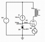
Following on experiment posted here , I wonder if a better approach might be to run it as a grounded grid (ie drive the cathode). As the DA41 is set up for A2 with Vg = +20VDC / Ig ≈ 9mA the thought is to run it as shown with current source set for roughly double the expected grid current to make allowance for some fluctuation (the grid current is relatively stable over most of the planned range) with the zener (or LED etc) using the other 9mA.
Any precedent for this way of doing it? I do intend to try it but am very interested to know if anyone here has tried this or not. My understanding is that A2 grid current is always from grid to B+ whereas grounded grid current -if any- would be from ground to grid, so my thinking is that this approach takes care of both.
Thanks !
Attachments

Last edited:
No, grid current flows from grid to cathode in either configuration.My understanding is that A2 grid current is always from grid to B+

Anyone have an LTSpice model for the DA 41? Got inspired to practice some and simulate this fairly simple circut 🙂
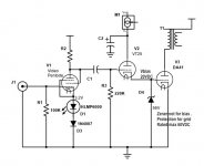
This is where UNSET started several years ago. In it's current configuration UNSET applies a resistive divider from plate to grid to ground creating a "Schade" feedback path and putting a positive voltage on the grid. A P-fet source follower stood on its head underneath the cathode provides drive and allows for adjusting the idle current. This began as an AC voltage source with a DC offset in LT spice.
If one desires to run the output tube as a pentode, the feedback voltage divider is substituted with a resistor or CCS to B+ and a Zener diode to ground as seen in your diagram. This has been tested with a resistor and Zener and confirmed to work.
One could also substitute a triode for the output tube and omit the screen supply which results in a circuit very similar to what's shown here. The only triode I had on hand that plugs right into the UNSET board was a 6CK4 which can and did go into A2 operation with the UNSET board running a fixed +9 volts on the grid via a 9.1 volt Zener diode in place of the feedback divider. The 6CK4 test was a "proof of concept" experiment to verify the idea. Power output was limited to a few watts to avoid melting the tube, as I only have a few.
The ultimate use case is to "tame" those "beam triode" regulator tubes like the 6HV5, 6HZ5 and 6JD5 which have a Mu of 300, a Gm of 55000, and a plate dissipation of 35 or 40 watts. So far I have created some powerful oscillators and TV jammers, but I have not yet tried to apply the feedback path with the bottom resistor tied to a positive voltage source (the zener / resistor) instead of ground. The necessary compactron socket was also connected into the octal board in a crude fashion which probably contributed to the oscillations.
The UNSET concept with its "Schade" feedback can linearize a pentode resulting in triode like curves. It can also be used to reduce the Mu of a high Mu triode, but testing has been limited in this regard. Further experiments are likely starting with a 6BL7 with both triodes in parallel.
Last edited:
Nothing new under the sun:
Best regards!
- A Cascode's upper valve is operated in grounded grid mode.
- Music Man's first amplifiers featured an output section where the grounded grid valves (6CA7) were driven by transistors between cathode and common ground.
Best regards!
In any triode when gronded grid is used, the cathode impedance will be seen into the anode as a ra = Ra + ( u + 1) Zk. Thus the impedance at the anode is notoriously increased looking backward from the load. Unless NFB is used, it implies much less damping for the speaker as in grounded cathode topology.
Grid current in a properly functioning vacuum tube should always be between the cathode and any of the grids. When grid current flows between one grid and another or any grid and the plate an abnormal situation exists. This is usually due to ionic contamination of the vacuum (called gas) or an overheated grid. I have found that overdriving any grid to the point of a glow when there is a higher positive potential on the plate will result in a grid current flow between that grid and the plate. This often results in a runaway condition, and the possibility of your tube turning into a flash - bang grenade. I scattered a couple tube all over the workbench before understanding this phenomenon.My understanding is that A2 grid current is always from grid to B+ whereas grounded grid current -if any- would be from ground to grid, so my thinking is that this approach takes care of both.
Sorry Jan, MY posted pic was incomplete. I had looked at the page linked from the first post and just assumed it would be obvious. I've changed the drawing on post one and will reppost the relevant material in this post.Why not just ground the grid? You need to bias the cathode positive anyway.
Jan
When I said that I had the so called "Dynamic Coupling " circuit linked in the first post in mind. Reposted below. There is no external path from the grid to ground, which is what I was referring to in my question.No, grid current flows from grid to cathode in either configuration.
I doubt it. Just use any tube that can be biased into A2-only mode.Anyone have an LTSpice model for the DA 41? Got inspired to practice some and simulate this fairly simple circut 🙂
Thank you ! This is the sort of info I was hoping for. It feels a little bit like drafting, at night , the guy in front knows the road real well, smooth ride for me.This is where UNSET started several years ago. . . . . . . . . .
TO Tubelab and all the other posters here. My fault in not considering the internal relationships when I said that. My question centres on the flow of current to or from the grid outside the tube , and in the case of the triode I've got on the breadboard , the cathode follower biases the grid up with (conventional) current from grid to B+ whereas the grounded grid relies on a low impedance path from ground to grid. That's what I was asking about .Grid current in a properly functioning vacuum tube should always be between the cathode and any of the grids. . . . . . .
Again, all the relevant details leading to the question (tube data sheets, load line, original papers on "Dynamic Coupling" circuit info, etc.) are in post #1 HERE.
Attachments
Actually, I missed that you can't ground the grid because then you can't cut off the tube.
So you need a pos grid bias so you can cut it off by dragging the cathode to ground. My senior moment ;-)
Jan
So you need a pos grid bias so you can cut it off by dragging the cathode to ground. My senior moment ;-)
Jan
Last edited:
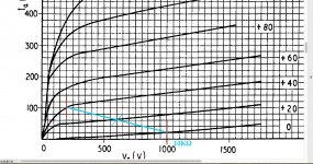
Hi Jan, it's a little different. I want to bias the tube up so it won't cut off . I only have a 10KΩ load for it and the best place to use it keeps the tube in A2, which was very convenient for the "Dynamic Coupled" topology I started with as within the load line limits (red) on the attached graph, the grid current stays pretty constant, something around 8 or 9 milliamps. As long as the swing doesn't go beyond those limits, then nothing tumultuous should happen soundwise. . . . . or that's my thinking anyway. : )
Attachments
Actually you only need a positive voltage on the grid to give the source in the cathode enough room to work in. The cathode must be pushed more positive than the grid to reach tube cutoff. The amount of this voltage depends on the tube in use.
Let's assume that the source feeding the cathode is an ideal interstage transformer with zero DCR. At idle the cathode would have zero volts and the grid would need to be biased negative for a typical vacuum tube biased in class A to keep the plate current to a safe value. Swap the tube for a "zero bias triode" or a tube designed for A2 operation like the 811A. Here the tube would draw very little if any current if there was zero volts on the grid and the cathode at any plate voltage under 500 volts. Any signal swing on top of that low bias point will push the tube into cutoff for most, or all of the negative half cycle of drive. This is what you want for a class C RF power amp for highest efficiency.
We want to stay well within class A2,,so some positive grid bias is needed to establish the desired idle current for a given plate supply voltage. As the 811A curves show, the grid current is not constant during the audio cycle however. The grid current swings up as the grid is driven positive with respect to the cathode, and it rises further as the plate voltage swings down. The driver must support this without distortion. This is where the Class A2 or class AB2 "sucks" stigma originated. Take it too far and you can blow up tubes. The 6L6GA (oldies) can crank out a very clean 100 watts per pair in class AB2 push pull into a 3300 ohm OPT on 500 volts. Push it to 110+ watts and a tube arc will occur. Been there, done that, twice!
UNSET replaces the ideal transformer, or ideal voltage source with DC offset with a P-fet follower. Fets can get nasty when operated at low voltages, so additional positive voltage is needed to keep the fet happy with 10 to 20 volts across it. The same may be needed here.
Many years ago there was a popular schematic circulating around the web that used a triode wired 6V6 driving the grid of an 811A in a manner similar to your dynamic coupled 2 circuit. It worked pretty well at low power output but got pretty ugly sounding if driven anywhere near clipping. I gave up on it after some tinkering, and eventually traded my 811A's to a ham radio operator.
Yeah, thanks . I was thinking last night in terms of sound it might be a better use of my time to abandon this tube. But for learning stuff it's working pretty well.
It did sound pretty good at the op point shown in the post above yours and after trying the "Dynamic. . .2" with a string of different drivers I did conclude that the best sound of the bunch came from the pipsqueak PC86, the highest GM driver of the ones I tried, and that sound still wasn't good enough.
Can't remember if I already said this or not but the best amp I've done from scratch on my own has been a grounded grid , interstage driving the cathode, so I thought before I abandon the DA41 I might as well see if it would like that way of working.
Writing this, I realize the PC86 , with highest GM tried, still isn't over the top in that department. Maybe I should give it another try with a higher GM type. e55L has 3 times the transconductance. . . . . .
One thing I haven't yet understood clearly is how the driver current in the "Dynamic" circuit translates to gain in the output tube. If the output grid is being held at +20V in this case, and grid current remains relatively flat across the range of swing, what's the mechanism of gain ?
I assume that the driver "injecting" current into the grid is forcing the grid up and down, yet testing the grid on its own shows that raising or lowering the voltage around the 20V bias point doesn't change the grid current by very much.
Is the load impedance the seen Vg-bias / Ig , in this case 20V / 8mA = 2500 Ω ?
Thanks
Last edited:
No, grid current flows from grid to cathode in either configuration.
Grid current in a properly functioning vacuum tube should always be between the cathode and any of the grids.
I get it now that the electron current that flows from ground to grid through the grid resistor is only considered to flow in undesirable conditions , and that any electron current that is acceptable is from cathode to grid . . . . . . but that means there must be a positive voltage source outside the tube to pull the current through , B+ or other positive supply. Does that mean that grid current associated with A2 biased operation is impossible with a simple capacitor or interstage transformer coupled circuit?
Attempting to drive the grid positive WRT the cathode will draw grid current. In a typical RC coupled circuit this current comes from the coupling cap, increasing the voltage stored across it, As the drive signal swings negative the increased voltage across the coupling cap will drive the grid further negative than it would ordinarily go if grid current had not flowed. Repeated attempts will further increase the voltage stored across the cap leading to what's called blocking distortion or "farting out" in guitar amp terminology. The usual cure in a guitar amp is to increase the value of the grid stopper resistor to limit the grid current.
An interstage transformer with a low DCR winding can work to drive the grid in an A2 or AB2 stage. In fact this was the preferred method many years ago.
An interstage transformer with a low DCR winding can work to drive the grid in an A2 or AB2 stage. In fact this was the preferred method many years ago.
But in the case of the interstage transformer, doesn't that mean that electron current will be drawn from ground through winding to grid to plate on positive grid V swings ?
Sorry to labor this , but I'm trying to stitch together the tiny snapshots I've got into a complete picture. This line of questioning all started with the fact that the "bad" (electron) current from ground to grid through the grid resistor that raises bias and causes runaway is called Grid Current just the same as is the one between cathode and grid. I built a misconception on the two sharing the same term (confusing) and now I'm trying to sort out the differences in a way I won't forget.
Sorry to labor this , but I'm trying to stitch together the tiny snapshots I've got into a complete picture. This line of questioning all started with the fact that the "bad" (electron) current from ground to grid through the grid resistor that raises bias and causes runaway is called Grid Current just the same as is the one between cathode and grid. I built a misconception on the two sharing the same term (confusing) and now I'm trying to sort out the differences in a way I won't forget.
Last edited:
A2 is not feasible with a capacitor coupled output stage. But transformer coupled A2 is very much acheivable since grid current can happily flow through the realtively low resistance secondary winding.Does that mean that grid current associated with A2 biased operation is impossible with a simple capacitor or interstage transformer coupled circuit?
Yes, there is 'forward' grid current which is normal when the grid is driven positive, and there is 'reverse' grid current which causes runnaway."bad" (electron) current from ground to grid through the grid resistor that raises bias and causes runaway is called Grid Current just the same as is the one between cathode and grid.
Grid current is the term used when current flows in the grid circuit whether it is intentional or not. In a perfect tube grid current only flows when the grid (any grid) is more positive than the cathode. We don't have perfect tubes, and some of today's new production tubes are farther from perfect that stuff from the "good old days."
No vacuum is perfect. There will always be some contaminants which could be air or other unwanted impurities. The metal and other materials used to make the tube are not perfectly pure either. Many of these impurities will ionize creating a blue, purple, or pink glow inside the plate. These ions can and do create a path for current to flow between any two elements in a tube. This unwanted grid current can pull the bias or screen grid voltage in a positive direction causing the plate current to increase which leads to more heat, impuritiy release and grid current. This often leads to a runaway condition.
Act like Tubelab and "make em glow" and these impurities will be released into the vacuum quickly. Run your tubes well within the ratings and the vacuum will still be contaminated, just at a much slower rate. Many years ago I bought some "NOS" 6BQ6GA's from AES and some of them were not quite NOS. I took a pair of well used "NOS" tubes that worked OK but looked dirty and ugly and attempted to see just how long they would last in "EXTREME" service. I don't remember the details but these guys were dissipating a lot of heat and making some serious power in a class A SSE amp. I set them on KILL and watched the show. Neither tube melted, but the power dropped and the distortion rose rather quickly. I believe that the total run time was an hour or two. The experiment ended when one of the cathode resistors went open and the associated bypass cap exploded.
Attachments
George, we mustn't forget that control grid current may also flow with zero bias, due to the electron cloud the grid is within. This is the reason why grid leak bias works with small signal tubes, mostly triodes: The - tiny - grid current through a high (10 to 22 MΩ) grid leak results in some small negative grid voltage.
Best regards!
Best regards!
Some tubes will start to show grid current with a small negative bias. I have seen this on some, but not many 12AX7's. Some frame grid TV IF amp tubes do this as well due to the close proximity of G1 to the cathode.
- Home
- Amplifiers
- Tubes / Valves
- A2 run as Grounded Grid