There was some initial interest in using Nelson's Zen I/V stage with the Saber DAC. I share this interest and to make it easier to follow, this thread will be dedicated to the Zen I/V adapted to the Saber.
The Saber32 9018 DAC chip from ESS has eight outputs that can be used as eight independent channels (surround sound anyone), or 4 outputs paralleled to make two channels, or even all eight paralleled into a mono channel per chip. I looked first at what it would take to make a single output from the Saber work with the Zen I/V, then a stero version. The 9012 and other Saber chips can also easily be used in the same ways, but I will concentrate on the 9018 for now.
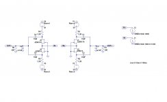
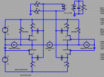
Here is the Zen I/V in stock form but with a second one added to form a balanced stage:
The 220 ohm and 1K resistors have been combined and the 220uf cap removed for clarity. Since the Simulation uses 0 ohms for the source impedance and there is no noise on the +/-30V supplies here, they do not contribute to the sim and can be added back once built depending on your tastes and what you feed this with. As in the original, 10mA P-P in results in approximately 2V RMS output.
More in the next post...
Dave
The Saber32 9018 DAC chip from ESS has eight outputs that can be used as eight independent channels (surround sound anyone), or 4 outputs paralleled to make two channels, or even all eight paralleled into a mono channel per chip. I looked first at what it would take to make a single output from the Saber work with the Zen I/V, then a stero version. The 9012 and other Saber chips can also easily be used in the same ways, but I will concentrate on the 9018 for now.
Here is the Zen I/V in stock form but with a second one added to form a balanced stage:
The 220 ohm and 1K resistors have been combined and the 220uf cap removed for clarity. Since the Simulation uses 0 ohms for the source impedance and there is no noise on the +/-30V supplies here, they do not contribute to the sim and can be added back once built depending on your tastes and what you feed this with. As in the original, 10mA P-P in results in approximately 2V RMS output.
More in the next post...
Dave
Attachments
"Stero" huh? My fat fingers apologize. I also wanted to invite feedback and recommendations/corrections. I have a good idea where I want this to go, at least for my purposes, but I would appreciate any help along the way.
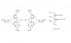
Here is a Zen I/V version for a single channel out of the Sabre:
The Sabre produces 3.903mA p-p per channel. This requires about 3K ohms in the upper and lower current resistors. This corresponds to a voltage output impedance of roughly 1.5K ohms. It begins to cause problems driving the first order filters (C3, C6 in this picture). The easiest way to reduce this effect is to decrease the value of the caps. I used 3.3nF as I also wanted to push the roll off up a little.
Also, the voltage must be increased for both rails as Mr. Pass pointed out. In this example I used 50V for some margin. This puts the puts the drain voltages about half of the +/-15V of the original, but with only 2/5ths the current in per channel.
Raising the voltage further does not appear to significantly help the performance and continues to increase the dissipation across the resistors R1/R4 and R4/R5, which is ~0.63W for this example.
The VCM input is intended to move the input offset voltage of the pair to match that of the Sabre DAC, 1/2 the analog VCC voltage. I am not sure if this is necessary, but it does appear to work in simulations. Perhaps someone with Sabre experience can comment on how the Sabre acts if it has to sink current?
Dave
Attachments
Last edited:
It would seem I cannot spell Sabre correctly either... Perhaps the moderator can fix the title for me? Thank you!
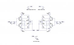
In order to handle the current of four channels in parallel (Stereo mode), it will take at least two pairs. Here is the variation I think some will like as it is very close to the original in operation and performance, without going to an extreme in parts. 🙂
Dave
In order to handle the current of four channels in parallel (Stereo mode), it will take at least two pairs. Here is the variation I think some will like as it is very close to the original in operation and performance, without going to an extreme in parts. 🙂
Dave
Attachments
Last one for a while, I promise -
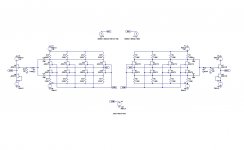
For those of you like me that want to see how far a simple idea can be extended, here is an over the top version of a balanced Zen IV for a stereo Sabre DAC. I think we should call this one "Group Zen". 😎
The power dissipation is again up as the rails and resistors have been increased appropriately.
I also wanted a buffer to drive any reasonable interconnect, so I added a buffer al-la Mr. Pass, although with dual supplies. Using a single supply and implementing it like the B1 is also completely acceptable with the addition of output capacitors. Since we have both source impedance and capacitance to ground at the gate of the input to the buffer, I am assuming that a gate resistor is not necessary...
If anyone sees any holes, please let me know!
Thank you Mr. Pass.

Dave
For those of you like me that want to see how far a simple idea can be extended, here is an over the top version of a balanced Zen IV for a stereo Sabre DAC. I think we should call this one "Group Zen". 😎
The power dissipation is again up as the rails and resistors have been increased appropriately.
I also wanted a buffer to drive any reasonable interconnect, so I added a buffer al-la Mr. Pass, although with dual supplies. Using a single supply and implementing it like the B1 is also completely acceptable with the addition of output capacitors. Since we have both source impedance and capacitance to ground at the gate of the input to the buffer, I am assuming that a gate resistor is not necessary...
If anyone sees any holes, please let me know!
Thank you Mr. Pass.
Dave
Attachments
Hi,
using 4 large caps to block DC and then generating offset in the output stage 😕😕
Why making a simple circuit more complicated, instead of using different parts that could handle the larger DAC-currents? There´s more on earth than just 2SK170s.
I don´t know if you call that a hole, but I know I wouldn´t do it that way.
Instead I´d design the caps much smaller, use different more current capable output JFETs, add 4 source resistances to the output buffers to get rid of the offset and maybe use a pair of MOSFEts or bipolars in the first stage.
jauu
Calvin
Last edited:
Hi Calvin,
The offset referred to is in the input, not the output. Specifically, the Sabre is powered from a single, positive supply. By using 1/2 AVCC from the Sabre as an offset (per the Sabre specifications) to the gates of the jfets, it ensures that the current output pins from the DAC are working where they need to be.
I also will be building one of these D1s to try for the Sabre as well. The simplicity of this jfet circuit is appealing to me, as is the sound character of jfets, so I want to build it and see what can be made of it with the Sabre and with a simple R2R DAC like the 1543...
Dave
dc offset correction? xfmr out?
I posted a sim with models, Ltspice asc file here:
Twisted Pear IVY shows using gnd as I/V voltage reference which gives ~8.5 mA current from the ESS9018 AVcc/2, this current needs canceling or offseting the Zen Vin to Vcc/2 would be a fine option
but if the ESS9018 really dosen't give up any perfromance in Vout mode I'd just fliter/buffer and skip the I/V
I posted a sim with models, Ltspice asc file here:
The Zen I/V does sim ridiculously well, IMD as low as -100dB – but who knows how good the jfet models are or how well any particular current out DAC performs with nonzero input impedance and offset
jfet parameter match dependance could be explored - I really expect the complete 2nd harmonic cancellation seen in sim with idendical models is impractical with real world device variation
There is offset of -124 mV at the I/V input with the nominal models and Nelson suggests a low Ohm pot V offset adjustment for mere mortals who don’t have hundreds of the fets to select the Idss matched pairs to get the 1 mV Vos he claims in his article, balanced I/V requires good matching of 4 fets
I show a sim with AC coupled xfmr (it could give selectable balanced or single ended output) to the degree that the caps match there is some psrr but filtered/regulated power is still a good idea
Cap physical size may be a challenge if you insist on film caps and low frequency response
Xfmr ratio, frequency response and Cload modification of the response are all details that need to be addressed
the current sources aproximate the PCM1794 +,- Iout, I show bias current cancellation R but not Vos adj
Twisted Pear IVY shows using gnd as I/V voltage reference which gives ~8.5 mA current from the ESS9018 AVcc/2, this current needs canceling or offseting the Zen Vin to Vcc/2 would be a fine option
but if the ESS9018 really dosen't give up any perfromance in Vout mode I'd just fliter/buffer and skip the I/V
Attachments
Last edited:
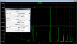
I am simulating a 2 tone balanced current input with dc bias from the PCM1794 data sheet
I like to look at IMD with 2 tone high frequency input as usually being most "stressful" distortion wise - the cs across the inputs is just a spice hack for balanced current excitation, the 2x 20KHz cs have opposite sign ac amplitudes
run the transient analysis and you should see 1:1 7KHz+20KHz output, I look at a 10mS long fft with Blackman window for good IMD product frequency resolution
Attachments
Last edited:
jcx,
Understood. Would this be simpler? It would also allow you to include the source imp from the DAC by adjusting the resistors. Those included here are for a 4x4 Sabre.
I will have to try this on the fully paralleled sim for the sabre.
Thanks,
Dave
Understood. Would this be simpler? It would also allow you to include the source imp from the DAC by adjusting the resistors. Those included here are for a 4x4 Sabre.
I will have to try this on the fully paralleled sim for the sabre.
Thanks,
Dave
Attachments

resistors would have to be in parallel with current sources, series with voltage sources
for the ESS9018 the Buffalo manual describes the analog out:
"Each analog output at 0DBFS is equivalent to a voltage of approximately 92.4% of AVCC in series with 195[Omhs]. So given 3.3VDC AVCC it will be about 3.05Vpp across 195[Omhs]. The output will be DC biased at AVCC/2. This works out to about 16ma peak to peak at each output. The amount of bias current will depend of the voltage of the virtual ground."
http://www.twistedpearaudio.com/docs/digital/Buffalo_II_User_Manual_v1.0.pdf
jcx,
Yup, drew them incorrectly as current. I will use voltage sources with resistors to simulate the intermod sources. Thanks!
I use 15.612mA p-p for the simulations run to date (Sabre32 9018 in 4x4 stereo mode). This number is the typ number directly from the 9018 datasheet.
Dave
Yup, drew them incorrectly as current. I will use voltage sources with resistors to simulate the intermod sources. Thanks!
I use 15.612mA p-p for the simulations run to date (Sabre32 9018 in 4x4 stereo mode). This number is the typ number directly from the 9018 datasheet.
Dave
Just an update on this project. I think I have a reasonable solution for Balanced to SE conversion on the Zen IV for balanced DACS like the Sabre. You can read about it here. Additional details about the circuit are here.
Enjoy!
Dave
To the moderator - I hope I am not breaking forum rules by pointing to other threads like this. It is an attempt to keep from polluting threads with off subject conversations while not repeating a bunch of information in multiple places... let me know if I am. Dave
Enjoy!
Dave
To the moderator - I hope I am not breaking forum rules by pointing to other threads like this. It is an attempt to keep from polluting threads with off subject conversations while not repeating a bunch of information in multiple places... let me know if I am. Dave
Last edited:
- Status
- Not open for further replies.
- Home
- Amplifiers
- Pass Labs
- A Zen I/V variant for the Saber DAC