Hi guys, a friend ask me to make a valve amp for him, I want to use WE-91B, since his speaker is TAD2402(sensitivity:93dB). He want to use 300B, so I think WE-91B is a good choice

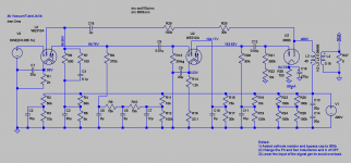
this is the circuit I draw in Altium Designer, because I want to make it into PCB

some of the components has been set to 91B accroding the original schematic
It is impossible for to collect the original WE components to make this amp, so I deceided to use morden components to make it.
this is the circuit I draw in Altium Designer, because I want to make it into PCB
some of the components has been set to 91B accroding the original schematic
It is impossible for to collect the original WE components to make this amp, so I deceided to use morden components to make it.
Like most of the DIY 91A builds, you won't need the input transformer or the first 310A. A single 6J7/6C6/310A will drive a 300B.
The WE-91B is used in excitation speaker system, so there is no choke in the schamatic, I have read some article said the excitaion speaker system will consume about 100V of the power source
Like most of the DIY 91A builds, you won't need the input transformer or the first 310A. A single 6J7/6C6/310A will drive a 300B.
I want to keep the first 310A to keep the original circuit as possible, and add a attenuator between the pre and 91B
first of all, deceided the power trans T3(359A)

the WE documents of 359A

prim: 110V+120V
sec:492.5+492.5/130mA
10V/1.2A(for 310A*2)
5V/2A(for 274B)
5V/2.4A(for 300B)
since I will not use 91B in excitaion speaker system, it is not necessary to keep 492.5+492.5
my design is
prim:220V
sec:400V+400V/130mA
10V/1.2A(for 310A*2)
5V/2A(for 274B)
5V/2.4A(for 300B)
the WE documents of 359A
prim: 110V+120V
sec:492.5+492.5/130mA
10V/1.2A(for 310A*2)
5V/2A(for 274B)
5V/2.4A(for 300B)
since I will not use 91B in excitaion speaker system, it is not necessary to keep 492.5+492.5
my design is
prim:220V
sec:400V+400V/130mA
10V/1.2A(for 310A*2)
5V/2A(for 274B)
5V/2.4A(for 300B)

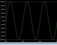
this is the final schamatic, ready for simulation.
I used the ayumi's SPICE model of 310A and 300B, it is quite accurate

View attachment WE-91B.zip
I used the ayumi's SPICE model of 310A and 300B, it is quite accurate
View attachment WE-91B.zip


I believe it is actually NFB due to the way it is feed back to the screen instead of the grid, and taken from the plate of the output tube.
Note 7 seems to confirm this in stating that shorting the 70K feedback resistor results in 10dB less gain. Shorting the 70K feedback resistor allows more feedback.
Note 7 seems to confirm this in stating that shorting the 70K feedback resistor results in 10dB less gain. Shorting the 70K feedback resistor allows more feedback.
Thank you very much. Your correction is really helpful. Giving me more confidence to finish this project
Oops, you are right.I believe it is actually NFB due to the way it is feed back to the screen instead of the grid, and taken from the plate of the output tube.
Note 7 seems to confirm this in stating that shorting the 70K feedback resistor results in 10dB less gain. Shorting the 70K feedback resistor allows more feedback.
the Power Trans design:

a=38mm(EI-114),b=55mm
Prim:
220V~472T/0.54mm
230V~494T/0.54mm
Sec:
420V(1010T/0.285mm)~400V(962T/0.285mm)~0~400V~420V/160mA
5V/2.5A(12T/1.129)
2.5V(6T/1.129mm)~0~2.5V/2.5A
5V(12T/1.129)~0~5V/2.5A
a=38mm(EI-114),b=55mm
Prim:
220V~472T/0.54mm
230V~494T/0.54mm
Sec:
420V(1010T/0.285mm)~400V(962T/0.285mm)~0~400V~420V/160mA
5V/2.5A(12T/1.129)
2.5V(6T/1.129mm)~0~2.5V/2.5A
5V(12T/1.129)~0~5V/2.5A


- Home
- Amplifiers
- Tubes / Valves
- A WE-91B project