Hi,
I was looking at this schematic of Pierre Johannet published on "L'Audiophile" and called "Super Némésis Compensé", seen on this French site:
https://www.bonavolta.ch/hobby/fr/audio/2sk135se.htm#2SK135 Single-Ended 3

"To improve the bass response and use a transformer without an air gap (larger primary inductance), it uses a second primary winding to avoid saturation of the magnetic core. This primary is powered (without any signal) by a second 2SK135, the current passing in an opposite direction cancels the magnetic field of the first primary."
I was thinking about a compromise to avoid any extra power consumption: use a custom dedicated winding on the OPT to supply the driver of the SE power tube, then helping to avoid core saturation (air gap still needed).
Searching for possible previous examples of this idea, I've then found Philips EL3541 amp with a similar approach (look point 70):
![philips_el3541_recorder_sch.pdf_1[1].png](https://www.diyaudio.com/community/attachments/philips_el3541_recorder_sch-pdf_1-1-png.1091996/ "philips_el3541_recorder_sch.pdf_1[1].png")
I was planning to ask Toroidy a specific SE OPT, and I would like to ask what specifications are needed to be communicated to get this advantage on core saturation.
Thank you all,
Roberto
I was looking at this schematic of Pierre Johannet published on "L'Audiophile" and called "Super Némésis Compensé", seen on this French site:
https://www.bonavolta.ch/hobby/fr/audio/2sk135se.htm#2SK135 Single-Ended 3
"To improve the bass response and use a transformer without an air gap (larger primary inductance), it uses a second primary winding to avoid saturation of the magnetic core. This primary is powered (without any signal) by a second 2SK135, the current passing in an opposite direction cancels the magnetic field of the first primary."
I was thinking about a compromise to avoid any extra power consumption: use a custom dedicated winding on the OPT to supply the driver of the SE power tube, then helping to avoid core saturation (air gap still needed).
Searching for possible previous examples of this idea, I've then found Philips EL3541 amp with a similar approach (look point 70):
I was planning to ask Toroidy a specific SE OPT, and I would like to ask what specifications are needed to be communicated to get this advantage on core saturation.
Thank you all,
Roberto
I dont think this arrangement is intended to undo/minimize core saturation. As far as I know its function, together with R38, is to lower power supply hum. The amount of windings between point 70 and the bottom of the primary is very low.
This arrangement can be found in many tube radio's and other tube equipment of that era.
Here's a link to something you mean, using a push-pull OPT: Single Ended with quiescent current compensation (Menno van der Veen)
This arrangement can be found in many tube radio's and other tube equipment of that era.
Here's a link to something you mean, using a push-pull OPT: Single Ended with quiescent current compensation (Menno van der Veen)
Last edited by a moderator:
There was a trafo winder that added a third low voltage winding for DC cancelation, what was his name again??
The product of the winding proportion and the current should be the same for the anode winding and the cancelation winding. If you plan a 20:1 opt (3k2 in 8R) for a 6S4S (50mA current), the DC cancelation winding could also have a 1:1 relationship with the OPT, and you could feed the 1A of the cathode through it, fed from a CCS. Or do we get cathode feedback then?
The product of the winding proportion and the current should be the same for the anode winding and the cancelation winding. If you plan a 20:1 opt (3k2 in 8R) for a 6S4S (50mA current), the DC cancelation winding could also have a 1:1 relationship with the OPT, and you could feed the 1A of the cathode through it, fed from a CCS. Or do we get cathode feedback then?
Mesa Boogie has a guitar amp that has the option of going low-watt single-ended class-A and the trick is just having the one half of the push-pull pair idle but not receiving signal. The transformer used is non-gapped intended for push-pull.
I have some 5kohm OPT from Edcor and when driven by a 6AS7 only the larger part of the primary is used. The smaller part intended for ultra linear drive of a screen can be used to pull current the opposite way, and probably reduce core sat. Haven't tried it yet...
Edit: check it out: https://www.ampbooks.com/mobile/amp-technology/amp-patent-7173488/
Interesting. The cathode feedback may be a good thing too, or just bypass the cathode since it is only the DC current you want for the core saturation cancellation.There was a trafo winder that added a third low voltage winding for DC cancelation, what was his name again??
The product of the winding proportion and the current should be the same for the anode winding and the cancelation winding. If you plan a 20:1 opt (3k2 in 8R) for a 6S4S (50mA current), the DC cancelation winding could also have a 1:1 relationship with the OPT, and you could feed the 1A of the cathode through it, fed from a CCS. Or do we get cathode feedback then?
Not tested! In this case I used the secondary itself as DC cancelation winding. Seems the phase is good for Cathode feedback (if wanted).
Ah don't think that's a good idea. You will get an offset voltage on the sec...
You need a separate winding.
You need a separate winding.
I agree about the offset - but how much is bad? 100mV for a .1R secondary? Anyway, I was being selfish 🙂 as I have a cap on the output for the highs in my biamp system.Ah don't think that's a good idea. You will get an offset voltage on the sec...
You need a separate winding.
Thanks all.
So if I have an idle current of 100 mA for the output tube and say 33 mA for the driver, the winding on the OPT must have three times the number of turns. In my design I have a CCS for the driver, so the DC cancellation should be stable too.
So if I have an idle current of 100 mA for the output tube and say 33 mA for the driver, the winding on the OPT must have three times the number of turns. In my design I have a CCS for the driver, so the DC cancellation should be stable too.
Zintolo,
The Important thing is that the cancelation winding should be fed from a high impedance, so that it does not form a short circuit for the AC (the music) developing across the primary winding.
There was a high amount of discussion about this DC cancelation techniques here at diyaudio, there are a lot of options available that do not lead to (a lot of) energy waste and unnecessary heat.
Erik
You cannot use same transformer for both driver and output... Or is your idea the driver circuit will have that winding bypassed so there is no signal and only passing DC current? You cannot do that since that will short the entire transformer.
BTW, I don't see the point of the Philips circuit in regards to OPT core saturation...? Isn't it just an ultra linear connection?
BTW, I don't see the point of the Philips circuit in regards to OPT core saturation...? Isn't it just an ultra linear connection?
Just realized you cannot bypass the cathode winding since that'll short the entire transformer. So in this circuit you must use the cathode winding as feedback, but that's no bad idea.Interesting. The cathode feedback may be a good thing too, or just bypass the cathode since it is only the DC current you want for the core saturation cancellation.
Dave Slagle of intactaudio offers transformers with offset windings for DHTs used with (high impedance) Coleman regulators.
Maybe you could also just wind your transformers with a big enough core?
Maybe you could also just wind your transformers with a big enough core?
The OPT has an ultra linear winding labelled 23-27 but TS meant the part of the primary between point 70 and R38. See my post #2.BTW, I don't see the point of the Philips circuit in regards to OPT core saturation...? Isn't it just an ultra linear connection?
I did this cancellation using a winding similar to the output winding to pass the filaments current .
In this way you don't need a large winding that would occupy useful space .
I used a CCS for filaments so no audio is wasted ( shorted ) by that winding .
Of course for a perfect cancellation you need to calculate very well the number of turns knowing the current , but even a partial cancellation improve the low frequency response quite a lot .
JC Morrison used a technique in a preamp design called "half-dead" buffer as described in his blog.
Now, I don't know if this can apply to a POWER amp. It certainly will draw just as much power as a push-pull amp and probably involve using two plate chokes or a center tapped choke (or the primary of a PP output transformer) whether acting as cathode follower or grounded cathode amp. It's a lot of iron to save one coupling capacitor!
Now, I don't know if this can apply to a POWER amp. It certainly will draw just as much power as a push-pull amp and probably involve using two plate chokes or a center tapped choke (or the primary of a PP output transformer) whether acting as cathode follower or grounded cathode amp. It's a lot of iron to save one coupling capacitor!
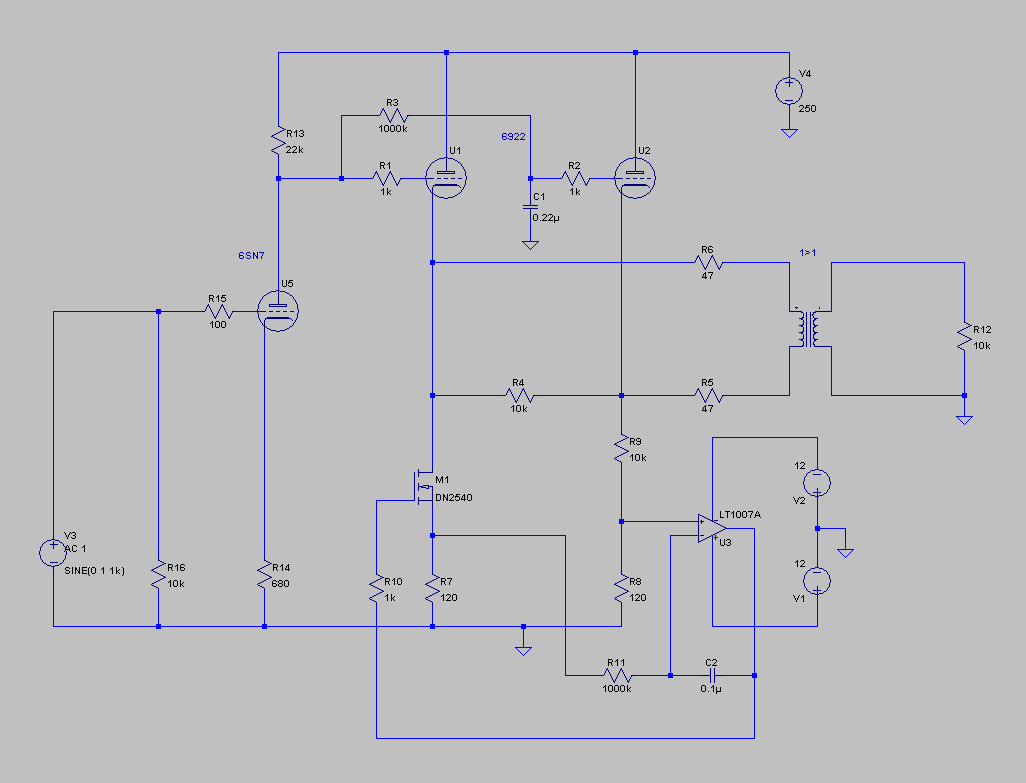
Here is the slightly fancy line amp application. This can be built as is. What you see here is a single grounded cathode gain stage – a 6SN7 in this case, although we have typically used WE262-A,B,C, 6900 or a 12AY7. followed by… “what is all that unnecessary crap?” or, “it’s a push pull circuit! run away!!!”. “what’s the big deal”, you might say… and there isn’t one. but it is very simple, reliable and useful. I hope you are looking at the second half of the arrangement. It is a single ended direct coupled buffer driving a single ended transformer. “what?!” Yes. The second half of the 6922 is a servo. a DC amplifier. The first half is the basic cathode follower. The second half 6922 simply strips the signal out and follows the DC of the first tube’s plate voltage. Both halves are operating as cathode followers, and the current source is also servoed so the two halves track more precisely. The punchline is: there are nano amperes of current in the winding of the un-gapped transformer, which is typically used in no DC service. Normally tubes drift and vary from one another quite a bit. they change constantly over their working life, in the negative direction, which has generally left them to the ridicule of many a know-it-all brick-for-brains engineering rube. It is clear, every circuit should be as independently self regulating as one can make it. The servo adjusts the reference point for the load (the transformer) over time so no DC current is allowed across the winding of the transformer.
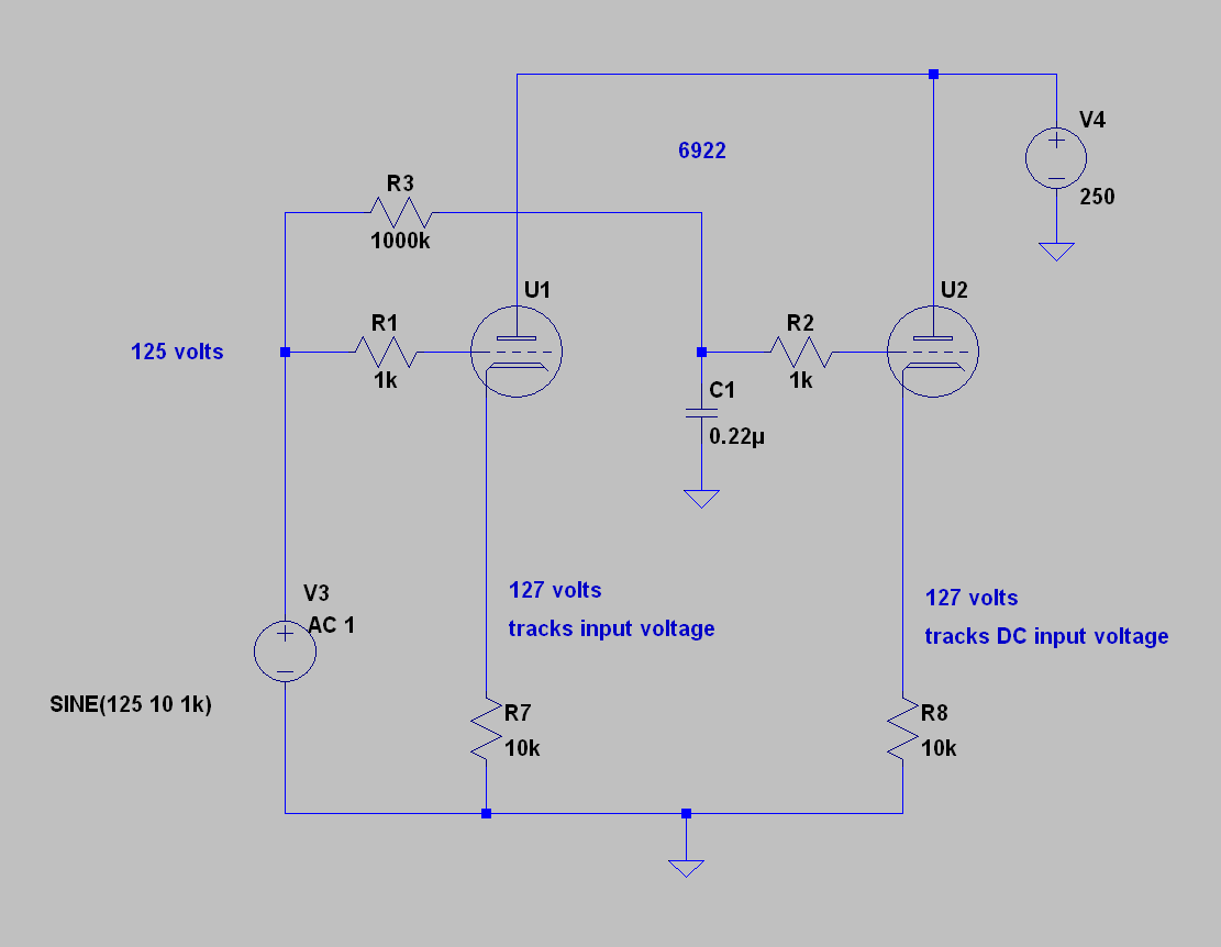
One could use a gapped transformer (that will handle the range of offset voltage/current) and simplify the circuit (get rid of the current source servo on U2). In fact I can hear Dave Slagle yelling in my ear that this is clearly the only sensible course of action… Ha! And then again, he might not? However, it is my experience that costs too much in terms of low and high frequency extension and changes in the time domain, too. if you already have single ended transformer coupled amps, and now also a preamp with a similar bandwidth. They can also change behavior with loading or signal level. In any case, if you want to try this idea without the servo, you can use any typical gapped interstage single ended transformer that can handle 0-30mA, for most of the tubes people tend to prefer these days. The main advantage of this circuit is that one can drive an un-gapped, nickel, amorphous, or iron-cored transformer (or all of the above at the same time) without the worry of saturation. Why is that such a good idea? Because making a closely coupled transformer with a high perm core material translates into lots of detail and isolation from power and environmental factors. And with this circuit, you can directly couple a single interesting historical amplifying device of your choice, to a buffer that couples to the load through your fancy transformer. without a center tap or unbalanced DC current in the windings. and the buffer keeps the load away from the voltage amplifier.
And here is the core idea of the “bankill cell” (“bankill” is a Korean pun… “half dead”). R3 and C1 form a very long time constant that filters out all audio, but not slow or DC variations. The cathode of U2 is free to follow the DC level of the signal input, which is ideal for another tube stage. If the two tubes share the same envelope and heater, they will drift together with temperature or power supply variations. We use this technique all the time to directly couple one stage to the next. The servo creates a “floating ground” for whatever comes next. But it works and is simple. I hope it helps someone out there!
I’m in the middle of a field in countryside, so please forgive my sketch on “cheese paper” as we say in Italy. This is the basic idea, but I will search other threads you mentioned that already talked about this topic. I'm very interested.

Last edited:
You realize thats a 1:3 step up relative to the output tubes swing? The signal level at the 10kohm resistor will be quite large, and the 10kohm will look like 10k/9ohms to the primary. And you are placing quite a burden on the transformer winder, poor fella. Good OPT are a work of art, interleaving windings and separating windings and all the details to get the lowest leakeage inductance and interwinding capacitance etc.
I think the mentioned idea of just using a properly dimensioned core is a simpler and better solution.
The notion of 'better bass' b/c the other winding is cancelling the core sat is b/c they are using a too small ( no gap) core, and the remedy in that case was that trick. Using a proper core to begin with does the same for bass.
That low current ( some miliamps ) would need much more turns than the primary itself in the compensation winding , I would say it is a dead end .
That's why I used the filament current , much higher current = much lower number of turns
That's why I used the filament current , much higher current = much lower number of turns
Last edited:
There was also a permanent magnet concept proposed to achieve the required bias of the B-H curve such that an SE stage at idle moves the B-H curve effectively back to B-H 0,0 origin. I can only anticipate that a thin shim Neodymium style magnet would be placed in the gap, although the gap may practically need to be wider than typically used to achieve enough bias, so incremental inductance may suffer too much.
Wrt vintage amps, Hammond type 52 and 62 OTs provided a 3% tapping for use in an SE output stage where the B+ supply has significant ripple voltage, and the 3% portion of the output transformer primary winding was used to neutralise (humbuck) the ripple voltage seen across the main portion of the OT primary winding. Neutralisation aims to equate the winding turns and ripple current products (N.I) for each portion, and the ripple voltage magnitudes seen at each end of the primary winding due to ripple current (anode resistance by ripple current in that portion equates to RC filter resistance by ripple current into preamp/screen supply for the Philips EL3541 schematic in post #1). The ECL82 has a plate resistance of circa 16k, and the filter resistance is 2.2kΩ, so a 2.2/16 = 14% tapping may be anticipated. The winding turns and DC current product (N.I) through the bias winding provides insignificant offset to the DC idle bias current in the SE output stage, so there is negligible benefit for core saturation effects.
Wrt vintage amps, Hammond type 52 and 62 OTs provided a 3% tapping for use in an SE output stage where the B+ supply has significant ripple voltage, and the 3% portion of the output transformer primary winding was used to neutralise (humbuck) the ripple voltage seen across the main portion of the OT primary winding. Neutralisation aims to equate the winding turns and ripple current products (N.I) for each portion, and the ripple voltage magnitudes seen at each end of the primary winding due to ripple current (anode resistance by ripple current in that portion equates to RC filter resistance by ripple current into preamp/screen supply for the Philips EL3541 schematic in post #1). The ECL82 has a plate resistance of circa 16k, and the filter resistance is 2.2kΩ, so a 2.2/16 = 14% tapping may be anticipated. The winding turns and DC current product (N.I) through the bias winding provides insignificant offset to the DC idle bias current in the SE output stage, so there is negligible benefit for core saturation effects.

- Home
- Amplifiers
- Tubes / Valves
- A way to help core saturation in SE