As PCM56,PCM1700,PCM58,AD1865,AD1862 and so on which all have the bipolar zero error. But if you use two of PCM56, one for high 15 bits data convert and one for low 15bits data convert, it can get rid of bipolar zero error.
For example, if you input data MSB is 1, for example 1101010010001010, the low 15 bits data converter will convert data 1101010010001010, and the high 15bits data converter will convert data 0000000000000000. If input data MSB is 0, for example 0101011010111110, the low 15 bits data is 1111111111111111, the high 15bits data is 0101011010111110.
And we add the two converters current to output. In this way, the MSB data of two PCM56 will not change, so we can get rid of bipolar zero error.
ragards,
it's the output error when Bit 1 on to off (or off to on)
when input data change 0000 to 8000 (or 8000 to 0000), it may cause more than 1 LSB error. It's not the DC offset.
when input data change 0000 to 8000 (or 8000 to 0000), it may cause more than 1 LSB error. It's not the DC offset.
AD1865 said:As PCM56,PCM1700,PCM58,AD1865,AD1862 and so on which all have the bipolar zero error. But if you use two of PCM56, one for high 15 bits data convert and one for low 15bits data convert, it can get rid of bipolar zero error.
For example, if you input data MSB is 1, for example 1101010010001010, the low 15 bits data converter will convert data 1101010010001010, and the high 15bits data converter will convert data 0000000000000000. If input data MSB is 0, for example 0101011010111110, the low 15 bits data is 1111111111111111, the high 15bits data is 0101011010111110.
And we add the two converters current to output. In this way, the MSB data of two PCM56 will not change, so we can get rid of bipolar zero error.
ragards,
The PCM63 and PCM1702 do indeed have nice datasheets. Pity they left out the control logic.
Well, if they had read the datasheet.....
Even if the glue logic isn't shown.......
They explain how "sign-magnitude" works, and there is a nice block diagram showing 2 DACs. Doing just what he describes.
AD1862 has a slightly different approach.
No need to reinvent the wheel when you can buy one the right way..............
Jocko
Even if the glue logic isn't shown.......
They explain how "sign-magnitude" works, and there is a nice block diagram showing 2 DACs. Doing just what he describes.
AD1862 has a slightly different approach.
No need to reinvent the wheel when you can buy one the right way..............
Jocko
Ok - I was looking for some help with an offset problem
Cheers AD1865,
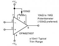
I am interfacing AD1865 with OPA627 as IV converter ( I like the sound, although I understand others don't)
I have a 40mV DC offset on the left channel and the suggested 100k trimmer helps a little, but not entirely.
Why am I getting this offset? (The trace to the inverting input runs through the chip legs- I suspect E-field coupling could be a problem)
Is there any quick and dirty method to trim opamp to zero?
(change the value of the pot?)
Help!

Cheers AD1865,
I am interfacing AD1865 with OPA627 as IV converter ( I like the sound, although I understand others don't)
I have a 40mV DC offset on the left channel and the suggested 100k trimmer helps a little, but not entirely.
Why am I getting this offset? (The trace to the inverting input runs through the chip legs- I suspect E-field coupling could be a problem)
Is there any quick and dirty method to trim opamp to zero?
(change the value of the pot?)
Help!
I guess the BurrBrown's Colinear (or Sign-Magnuite) approach is now patent free.
Anyone can make their own Sign-Magnitude DAC by designing their glue logic, serial to parallel interface, and banks of discrete R2R network. Just like what MSB Platinum Link and Lavry DA2002 did.
Anyone can make their own Sign-Magnitude DAC by designing their glue logic, serial to parallel interface, and banks of discrete R2R network. Just like what MSB Platinum Link and Lavry DA2002 did.
Bypassing- Thanks AD1865
Thanks AD1865,
I'll try bypassing across pins with ceramic.
Currently I'm using BG NX-NiQ without bypass because many pepole say that bypassing such capacitors ruins the sound.
We'll see if this helps...
BTW why might self-oscillation result in an apparent d.c. offset?
Thanks AD1865,
I'll try bypassing across pins with ceramic.
Currently I'm using BG NX-NiQ without bypass because many pepole say that bypassing such capacitors ruins the sound.
We'll see if this helps...
BTW why might self-oscillation result in an apparent d.c. offset?
These guys are describing their behaviour as sign-magnitude, which isn't 2's complement.They all use 2's compliment............
People are mentioning the zero error caused by the numerical discontinuity as the signal crosses from -ve to +ve. If indeed that is the problem, then surely use of a 2's complement architecture would resolve this?
it's not the numerical discontinuity
Because bit 1 ouput drift error over temperature and so on.
to oli,
Yes, the ceramic cap capacitors direct to op pin may ruins the sound. You'd better use polypropylene film capacitors and a 1 ohm resistance in series.
Because bit 1 ouput drift error over temperature and so on.
to oli,
Yes, the ceramic cap capacitors direct to op pin may ruins the sound. You'd better use polypropylene film capacitors and a 1 ohm resistance in series.
OliFilth said:
These guys are describing their behaviour as sign-magnitude, which isn't 2's complement.
People are mentioning the zero error caused by the numerical discontinuity as the signal crosses from -ve to +ve. If indeed that is the problem, then surely use of a 2's complement architecture would resolve this?
All current dacs are 2's complement and the problem stems from that. Sign Magnitude in this context refers to the technique used by Burr-Brown, now TI, to make the step from BPZ to BPZ-1 the same as all other steps. It involves conversion from 2's complement to sign-magnitude and two straight binary dacs.
What is being proposed is to copy BB's work by making a single dac from two half dacs and some glue logic. If the large step is giving you sleepless nights, just buy a PCM63, PCM1702 or PCM1704.
rfbrw said:If the large step is giving you sleepless nights, just buy a PCM63, PCM1702 or PCM1704.
Technics SL-P770 and others have PCM56+ and PCM56- per channel.
Ceramic doesn't do the trick!
Thanks AD1865, but...
Last night I experimented with ceramics directly across the pins.
The result.... no difference to d.c. offset. I expect that even if ceramics ruin the sound there should be some measurable outcome if oscillation was a problem.
I next replaced the AD1865N-K DAC with a spare. Now only 25mV of d.c.
I have cleaned all traces carefully to remove any grease from fingerprints or any flux.
Any other ideas?
Bernhard said:
Technics SL-P770 and others have PCM56+ and PCM56- per channel.
Merely having two dacs tells you nothing other than there are two dacs if you do not know what the preceding logic is doing.
rfbrw said:
Merely having two dacs tells you nothing other than there are two dacs if you do not know what the preceding logic is doing.
Yes, one outputs + halfwave and the other - halfwave.
Bernhard said:
Yes, one outputs + halfwave and the other - halfwave.
The beauty of not knowing something for certain is that one is free to believe anything one wants. If you want to believe this half wave stuff, be my guest.
- Status
- Not open for further replies.
- Home
- Source & Line
- Digital Source
- A way to get rid of bipolar zero error