He is not using the first placid... that is the a placid HD. It is true that since the original Placid has undergone a lot of change - but the version he has there should work just fine. 🙂
Last edited:
Yes - It is also true that the first version does suffer from a high degree of voltage offset from tempco. That was because of the choice for a minimal correction circuit - the new Placid is a far better in that regard (and others) it is true.
It sounds like things may not have been wired correctly from the transformer? Some pics of the power supply wiring could help narrow things down. 🙂
You should throw it out and either buy latest version or use another design dual supply.
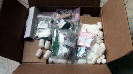
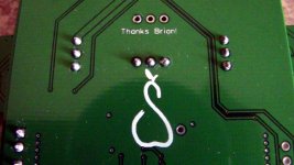
😱 Was I penny wise, dollar dumb buying this kit used? 😱 As I mentioned, I bought this kit on Swap meet, here on diyAudio in 2014. All the kit parts were still sealed, although I was missing the terminal blocks on the SPDIF kit, and was missing half the risers on the three tridents. I Ended up soldering the tridents directly to the lower riser. I hope that is okay. 😱 I also do not know if I have the new firmware chip or not on the DAC board. The person I bought this from had it for awhile also. The number on the chip is: TTINY85 20PU I am guessing this was one of the first Buffalo III boards.
Attachments
I think you did fine. 🙂 Lets just try to sort out the power supply. What transformers do you have and how did you wire them?
Thanks, Russ for helping me trouble shoot this...
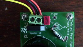
I hope so... I Have the Placid HD version 1.
So there is no way to "modify" the version 1... I am guessing the newer designs are a completely different layout. Do the newer boards use some of the same components? If I do invest in the newer boards, I might want to keep the older version around for replacement parts. ???
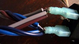
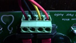
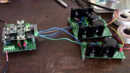
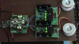
Here are the wiring photos from the transformers. As I understood from the manual, is red and yellow are the "live" wires from the secondaries and the brown and gray are the "live" wires on the primary. The Placid BP had S1A, S1B, S2A, and S2B. Yellow is in S1B and Red is in S2B, these could indeed to be backwards. Should Yellow be in S1A and Red is S2A?
I cut a little much off on one of the blue primary wires, as You can see in the photo. I did not want to cut the wires down to size until I have the chassis. So this will be redone for the final build.
I would also consider buying the new Placids, but I would really like to see how I am going to like this DAC first.
Thanks again for your help, Russ
- but the version he has there should work just fine. 🙂
I hope so... I Have the Placid HD version 1.
Yes - It is also true that the first version does suffer from a high degree of voltage offset from tempco. That was because of the choice for a minimal correction circuit - the new Placid is a far better in that regard (and others) it is true.
So there is no way to "modify" the version 1... I am guessing the newer designs are a completely different layout. Do the newer boards use some of the same components? If I do invest in the newer boards, I might want to keep the older version around for replacement parts. ???
It sounds like things may not have been wired correctly from the transformer? Some pics of the power supply wiring could help narrow things down. 🙂
Here are the wiring photos from the transformers. As I understood from the manual, is red and yellow are the "live" wires from the secondaries and the brown and gray are the "live" wires on the primary. The Placid BP had S1A, S1B, S2A, and S2B. Yellow is in S1B and Red is in S2B, these could indeed to be backwards. Should Yellow be in S1A and Red is S2A?
I cut a little much off on one of the blue primary wires, as You can see in the photo. I did not want to cut the wires down to size until I have the chassis. So this will be redone for the final build.
I would also consider buying the new Placids, but I would really like to see how I am going to like this DAC first.
Thanks again for your help, Russ
Attachments

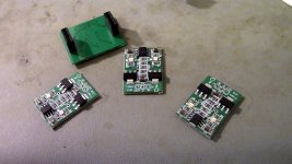
Regular Placid rectifier
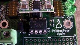
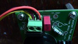
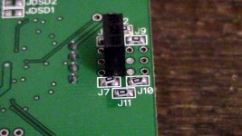
Here was the cold solder joint I found on J7 on the DAC board. Would this cause the rectifier to hiss and smoke?
As I mentioned in post #9, I had both supplies running fine for three hours, at full power, bypassing the bulb in the bulb tester. This was without a load, however. The issues came up when I hooked up the loads. Everything seemed okay thru the bulb tester, but I should have checked those outputs on IVY also. It was when I bypassed the bulb when things went haywire...
Attachments
There is a difference between the "Placid" and the "Placid - HD" two different circuits. 🙂
New placid HD's use a completely new circuit with a precision voltage reference - you would need new parts.
The placid HDs (version 1) you have right now should serve you well as long as they have not been damaged 🙂
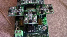
The transformer wiring looks good - but the solder joint on one leg of R1 looks suspect.
I would double check them all - then test the supplies independently. If you have a suitable dummy load (something like a 1-2W 50R resistor will work well for 5V 100ma) even better!
New placid HD's use a completely new circuit with a precision voltage reference - you would need new parts.
The placid HDs (version 1) you have right now should serve you well as long as they have not been damaged 🙂
The transformer wiring looks good - but the solder joint on one leg of R1 looks suspect.
I would double check them all - then test the supplies independently. If you have a suitable dummy load (something like a 1-2W 50R resistor will work well for 5V 100ma) even better!
Here was the cold solder joint I found on J7 on the DAC board. Would this cause the rectifier to hiss and smoke?
No.
The only thing I can think of that would have cause that would be a short right after the rectifier.
Thanks Russ,
I will check everything tomorrow or the week-end. I got five meals packed, ready to do a 13 hour day. Two jobs and a side business is not easy sometimes...
I will check everything tomorrow or the week-end. I got five meals packed, ready to do a 13 hour day. Two jobs and a side business is not easy sometimes...
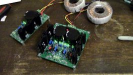
It Plays!
I am happy to report that I have Music playing!
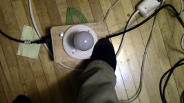
As it turns out, my problem was flux residue. Russ gave me the clue:
Quite a bit had wicked to the top side of all the boards into some impossible to reach areas. A though cleaning with brushes and tooth picks was not good enough. Flux is a lot like grease, it spreads and smears, causing Mega ohm connections between terminals where there should not be. Part of this was caused by my technique, and part by the flux I used. I will go into that at a later date in greater detail when I have more time. How I solved the problem was, first brushing generous amounts of alcohol on the boards, getting in every nook and cranny. That was immediately followed by a raise with hot water. I used the spritzer on my kitchen sink at 1.6 gallons per minute to "power wash" the boards. 😱 That was followed by a second cleaning with CJ Flux Remover, and a second "power wash" raising. Then I used a hair dryer to dry the boards as much as I could. Finally, the boards where placed in a preheated 170 degree oven. The turned the oven off, as soon as I inserted the boards, and left then to dry overnight. The next day, I probed the boards and did not find any more Mega Ohm readings.
I at listening to music now, so this must have worked! 🙂
I can say, Russ and Brain have created a durable piece of kit, to go thru what I have put this through. This should also prove that ANYBODY can build this thing! I will go into greater detail and continue posting pictures of the build when the time is available.
At this time, I am more interested in sharing my first listening impressions. 😉
Will be starting the 13 hour days again tomorrow, so getting as much listening in as I can today. Music is actually starting to sound more like... Music! This DAC takes what my First One amp does so well with details, textures and layers; and allows it to dig even deeper. There is texture on the texture and layers in between the layers. Drums, esp snare and hand drums sound the way I hear them when I am helping musicians I know record them. Piano and vocal harmonies are amazing. The music is starting to sound "real"
Blu-ray Movies are equally impressive. In some mixes, the dialog can get lost in a 2 channel mix-down, but that is not the case with the Buffalo III. It "layers" complex material really well. The dialog might be quiet, compared to the earthquake around it, but I can hear what they are saying, along with the reflections their voices in the space they are in. All of this is recording permitting, of course. What I really like, is I can hear down into the sound. What I mean, is I do not have to turn the system up to hear the details and get the "live" sound, it is there at lower levels also. Do not get me wrong, going LOUD is amazing, and this DAC does dig deeper if the recording permits, but is does not have to be loud all the time. 😀
Coming into this build, I was not sure if this was going to be the best DAC with First One, and I am sure many of You have read about the super high end market knocking the mid-range of the Delta Sigma DACs, esp the ESS Sabres. But I can say, I do not feel the mid-range lacking at all. I am coming from an M-Audio fast track pro, so maybe my bar is not set so high, but I am enjoying this DAC at the moment with the IVY. Maybe down the road I will try tubes, yet maybe I do not have to.
Bare in mind, I am using full-range line array speakers and I have them EQed to my room using FIR based DSP in JRiver. So I may not need to "voice" my output stage as others do. I will also mention, I normally run my arrays with two subs in a four channel configuration. Can not do that with this current set-up, so I am running my arrays from 40 Hz on up. I miss the lowest octave on some material, but the gains of this DAC are worth the trade-off.
off to work now...
I am happy to report that I have
Music playing! As it turns out, my problem was flux residue. Russ gave me the clue:
The only thing I can think of that would have cause that would be a short right after the rectifier.
Quite a bit had wicked to the top side of all the boards into some impossible to reach areas. A though cleaning with brushes and tooth picks was not good enough. Flux is a lot like grease, it spreads and smears, causing Mega ohm connections between terminals where there should not be. Part of this was caused by my technique, and part by the flux I used. I will go into that at a later date in greater detail when I have more time. How I solved the problem was, first brushing generous amounts of alcohol on the boards, getting in every nook and cranny. That was immediately followed by a raise with hot water. I used the spritzer on my kitchen sink at 1.6 gallons per minute to "power wash" the boards. 😱 That was followed by a second cleaning with CJ Flux Remover, and a second "power wash" raising. Then I used a hair dryer to dry the boards as much as I could. Finally, the boards where placed in a preheated 170 degree oven. The turned the oven off, as soon as I inserted the boards, and left then to dry overnight. The next day, I probed the boards and did not find any more Mega Ohm readings.
I at listening to music now, so this must have worked! 🙂
I can say, Russ and Brain have created a durable piece of kit, to go thru what I have put this through. This should also prove that ANYBODY can build this thing! I will go into greater detail and continue posting pictures of the build when the time is available.
At this time, I am more interested in sharing my first listening impressions. 😉
Will be starting the 13 hour days again tomorrow, so getting as much listening in as I can today. Music is actually starting to sound more like... Music! This DAC takes what my First One amp does so well with details, textures and layers; and allows it to dig even deeper. There is texture on the texture and layers in between the layers. Drums, esp snare and hand drums sound the way I hear them when I am helping musicians I know record them.
Piano and vocal harmonies are amazing. The music is starting to sound "real" Blu-ray Movies are equally impressive. In some mixes, the dialog can get lost in a 2 channel mix-down, but that is not the case with the Buffalo III. It "layers" complex material really well. The dialog might be quiet, compared to the earthquake around it, but I can hear what they are saying, along with the reflections their voices in the space they are in. All of this is recording permitting, of course. What I really like, is I can hear down into the sound. What I mean, is I do not have to turn the system up to hear the details and get the "live" sound, it is there at lower levels also. Do not get me wrong, going LOUD is amazing, and this DAC does dig deeper if the recording permits, but is does not have to be loud all the time. 😀
Coming into this build, I was not sure if this was going to be the best DAC with First One, and I am sure many of You have read about the super high end market knocking the mid-range of the Delta Sigma DACs, esp the ESS Sabres. But I can say, I do not feel the mid-range lacking at all. I am coming from an M-Audio fast track pro, so maybe my bar is not set so high, but I am enjoying this DAC at the moment with the IVY. Maybe down the road I will try tubes, yet maybe I do not have to.
Bare in mind, I am using full-range line array speakers and I have them EQed to my room using FIR based DSP in JRiver. So I may not need to "voice" my output stage as others do. I will also mention, I normally run my arrays with two subs in a four channel configuration. Can not do that with this current set-up, so I am running my arrays from 40 Hz on up. I miss the lowest octave on some material, but the gains of this DAC are worth the trade-off.
off to work now...
Attachments
Congratulations!
Hey Allen good to see you solved the issue. Now we have to figure what type of permanent enclosure or platform we are going to use. It seems this boards are bullet proof even radiation proof!
Hey Allen good to see you solved the issue. Now we have to figure what type of permanent enclosure or platform we are going to use. It seems this boards are bullet proof even radiation proof!
Ccs current and shunt current values
What values did you set the power supplies for?
The BP supply sinks were very hot so I turned down the ccs current to 260 ma and shunt to 130 ma. V out is 14.7 v.
For the HD supply I have a ccs current of 572 ma and a 0.002 ma shunt reading.
V out is 5.1 v.
I have not been able to to raise the shunt reading. It is sounding marvelous anyway.
Would I have to fiddle with the HD settings some more?
PSU settings, chassis and layout...
Hi Manolo,
I just retested mine with a moderately loud signal. Based on the manual, the IVY III uses 50-150 mA. I set the HD BP at about 240 mA which gives me about 160 shunt with a signal. In my case, I do not get different readings at all when running idle or pushing a signal. The voltage is at about 14.90 on each side.
I am surprised Your HD is set to 572 mA and there is so little shunt. I have mine set at 530 mA and I have about 72 shunt. And this is with a moderately loud signal. Idle is the same. I am also running the single SPDIF board off the HD. The Manual says the DAC board will need about 450 mA and the single SPDIF board needs an additional 10-15 mA, so I am pretty close. The voltage is right at 5.25. Maybe your voltage is too low, and the DAC is eating all the current it can get.
Hopefully Russ or someone will chime in...
The manual suggests having 50 mA shunt, so I need to readjust both supplies to waste less power. I will not be doing that until the weekend. I had a 13 hour work day today, another tomorrow and the next day - I do not want to chance an "accident". 😉
As far as a chassis, I got some other things to figure out first. I would really like to eventually go 4 channel, so ideally I would like to build another kit and will need to reset this build for an I2S signal. I am not sure how I am going to extract the multi-channel signal from my PC. I might use the teleporters, or I could try one of the newer USB boards. Either way, it would be nice to have the two DAC kits in one full width chassis. The bad part, is I am in no hurry, and may end up building my next full-range line array speaker prototype. (I have all the materials for that project, no need to spend any $$$.) If that goes well, I may not need four channel for awhile. The bad part, is I do not like having a "naked" DAC as it is now. 😱
That aside, I do have some questions about chassis and layout.
First off, what is the ideal material for a DAC chassis? Steel, Aluminium, or Wood?
Also, How close can the DAC and IVY boards be to the PSU's?
How close can the Transformers be to the PSU's?
I am leaning towards one of the HIFI module chassis from the diyAudio store to match my First One Amp.
This DAC is a keeper for sure. 😀
Regarding enclosures the obvious one would be fabricated in aluminum. It would look more "professional", however, it would also make the project susceptible to vibrations though the boards would not be as isolated or damper as if mounted in an mdf or wood platform.
If I were to use an AL. enclosure I wouuld use a rather thick bottom plate and also would mount the transformers in a small wood interfaces between the pl. and transformer.
I guess I'll have to keep fiddling with the shunt current in the HD board some more. I measured it last night and it read -.002mv. ?....The unit is sounding better ekvery day.
Aluminum is the way to go. It will provide shielding and general physical protection. It is also easy to machine with wood tools. The boards are not sensitive to vibration, so I would not worry about that.
Hello Allen:
Congratulations on a successful build. Your experiences reminded me very much of my own when I did a couple of similar builds.
I started using 99.9% isopropyl alcohol for cleaning my boards but, as you did, I gave up on it and now I use flux cleaner. The flux cleaner just works so much better for me.
As far as an enclosure, I have used a model 20-16124x (4x16x12 inches) from Par-Metal I just used the basic brushed metal and it came to $100 with shipping. Many DIYers like the enclosures from modu and I will probably use these in the future also.
This thread will be appreciated by many new DIYers. I know when I do a build I'm looking for all the help I can get and the addition of the pictures is a great deal of help.
Enjoy the music!
- Status
- Not open for further replies.
- Home
- More Vendors...
- Twisted Pear
- A Visual Buffalo III Building Journey...