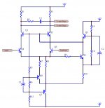
Today, I'm not so busy, than I have time to review technique paper in our company's tech-lib. I found a sch of a hi-fi power amp, and I spend many time in it. But I can not fully understand it's input yet.
I attach it below, does someone understatd it? I wanna know:
1. why the designer do so complex design,
2. what benefit with it,
3. and how to analyze it.
Thank in advance...
I attach it below, does someone understatd it? I wanna know:
1. why the designer do so complex design,
2. what benefit with it,
3. and how to analyze it.
Thank in advance...
Attachments
Konnichiwa,
You will have to ask teh designer. The circuit is pretty basic really.
To start simple, the main circuit is a cascoded long tailed pair (LTP), very ordinary though a good idea to improve circuit linearity. Part of the complexity is the Biasing for the Cascode Transistors (Q3 is a simple emitter follower biasing the bases's of the cascode).
The two PNP Transistors below the LTP together with Q6 are a cascoded/super pair current source (if I read the circuit right). So again, not much of an extraordinary design. Of course such a CCS is much more "constant" than simpler circuits.
I hope that helps a bit.
Sayonara
wenye said:I attach it below, does someone understatd it? I wanna know:
1. why the designer do so complex design,
2. what benefit with it,
You will have to ask teh designer. The circuit is pretty basic really.
wenye said:3. and how to analyze it.
To start simple, the main circuit is a cascoded long tailed pair (LTP), very ordinary though a good idea to improve circuit linearity. Part of the complexity is the Biasing for the Cascode Transistors (Q3 is a simple emitter follower biasing the bases's of the cascode).
The two PNP Transistors below the LTP together with Q6 are a cascoded/super pair current source (if I read the circuit right). So again, not much of an extraordinary design. Of course such a CCS is much more "constant" than simpler circuits.
I hope that helps a bit.
Sayonara
- Status
- Not open for further replies.