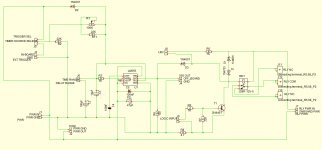
As I start building stuff, I find that I often want to have some kind of delayed connection or disconnection as part of a safety system or other operation. This is usually something that happens e.g. a startup of a power amp, where you want to take a resistor out of circuit, fade up the input, or connect the speakers only after a delay. There are certainly lots of ways to do this, but I also wanted to make a circuit that was both useful and versatile. I created a design based around a 555 timer IC configured as a single shot using the pin 3 output as a current sink, with pin 3 going high to low after the delay period has elapsed and allowing current to flow through the relay coil. This kind of circuit is very versatile and can be configured for delays ranging from under 100 msec to more than 100 seconds, depending on the choice of RC component values. You can read more about this type of circuit here:
555 TIME DELAY CIRCUITS
FUNCTIONALITY:
delayed activation of relay coil
adjustable time delay via C and trimpot, or fixed timing via selection of R and C
the 555 can be set to trigger at power up (internal trigger) or by an external input
on-board SPDT relay with D+Z kickback suppression
0.25" FASTON relay contact connections
unmasked relay contact PCB tracks that can be loaded with solder for higher current applications
LED indication can be located on board or externally
555 output routed to header for serial-triggering of multiple boards
power connections allow for easy daisy-chaining of multiple boards
3.3v/5v LOGIC signal input (separate from 555 trigger)
ability to configure board for constant current operation (see text for explanation)
relay coil power can be routed off-board for additional control
OVERVIEW:
The relay board can be used alone, or in multiples. When used in multiples, each board can be triggered by connecting the 555 output of one board to the external trigger connection of the next board or, if no delay is desired, to the logic input. This makes it easy to set up and adjust a series of boards to perform sequential tasks.
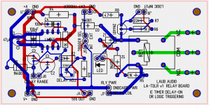
When populated with a 100k trimpot (R1) and 10uF (C1) and 100uF (C2) timing capacitors, the board can provide delays of either 75msec to 1.2 seconds (10uF cap only) or 750msec to 13 sec (both caps in parallel). A 2-pin header labeled "DELAY RANGE" lets the user switch between these two time ranges, the longer range being selected when the header is shorted by a jumper. Other choices for R and C can allow for whatever range of delays the user desires. If the desired delay is known, the user can simply populate resistor R11 with the required value in place of the trimpot.
The faston tab connections make it easy to connect to speaker or power supply wiring. The traces leading from the faston tabs to the relay pins are left without solder mask so that the trace thickness can be built up for higher current applications.
An LED that illuminates when the relay coil is activated can be connected via a header so that it can be located off board, e.g. on the user control panel, to display the relay status.
There is a header "RLY POWER" that allows the user to choose how the relay coil is powered. Normally this is populated with a jumper to connect the onboard power (e.g. 12Vdc) to the coil. This jumper also provides the option of routing the onboard power off board, through the NO contacts of another relay with a mains powered coil (e.g. 120VAC coil in USA), and then back onboard. One use for this arrangement is for a speaker output relay in an amplifier. During power up, the speaker relays are connected last, after the amp has settled, using the relay board. In the event of a power failure, or when power is switched off, the relay with the AC coil will immediately cut the power to the onboard relay, causing it to open and disconnecting the speaker. By connecting the coil power supply for multiple relay boards in this way, all via one AC-coil relay, a number of speaker connections can be opened simultaneously. This avoids having to wait for the relay power supply to collapse sufficiently for coil drop out to take place, and can provide very fast opening of the speaker relay contacts before any transients reach the speaker.
To prevent arcing and EM radiation, spark suppression of the relay coil kickback is done using both a diode and a 5.1V zener diode. Although this will only happen when the relay coil is DE-activiated, it should prevent turn off pops and extend the life of the circuit.
The board can be built up with some or all of the components, depending on the particular application, need for adjustability, and with/out the logic input and/or constant current operation. The full board with headers can allow for a wide range of delayed triggering applications in projects such as amplifiers and line level equipment where relays might serve a useful purpose and a PIC or microprocessor is not implemented.
CONSTANT CURRENT OPERATION:
One possibility for powering a circuit like this that requires less than 100 mA of current is a transformerless power supply (TPS). The output voltage of a TPS is strongly load-current dependent, and there is typically a large change in current when a relay coil is activated. To get around this problem the circuit board can be populated with an extra resistor that creates an auxilliary current draw when the relay coil is inactive. Then when the relay is activated, the auxilliary current flow ceases and all the current is delivered to the relay coil (and LED, if used). By choosing the auxilliary current demand to be approximately equal to that of the relay coil (and LED, if used) the current demand by the relay board is essentially constant regardless of the state of the relay coil, and the board can be powered by a TPS.
.
555 TIME DELAY CIRCUITS
FUNCTIONALITY:
delayed activation of relay coil
adjustable time delay via C and trimpot, or fixed timing via selection of R and C
the 555 can be set to trigger at power up (internal trigger) or by an external input
on-board SPDT relay with D+Z kickback suppression
0.25" FASTON relay contact connections
unmasked relay contact PCB tracks that can be loaded with solder for higher current applications
LED indication can be located on board or externally
555 output routed to header for serial-triggering of multiple boards
power connections allow for easy daisy-chaining of multiple boards
3.3v/5v LOGIC signal input (separate from 555 trigger)
ability to configure board for constant current operation (see text for explanation)
relay coil power can be routed off-board for additional control
OVERVIEW:
The relay board can be used alone, or in multiples. When used in multiples, each board can be triggered by connecting the 555 output of one board to the external trigger connection of the next board or, if no delay is desired, to the logic input. This makes it easy to set up and adjust a series of boards to perform sequential tasks.
When populated with a 100k trimpot (R1) and 10uF (C1) and 100uF (C2) timing capacitors, the board can provide delays of either 75msec to 1.2 seconds (10uF cap only) or 750msec to 13 sec (both caps in parallel). A 2-pin header labeled "DELAY RANGE" lets the user switch between these two time ranges, the longer range being selected when the header is shorted by a jumper. Other choices for R and C can allow for whatever range of delays the user desires. If the desired delay is known, the user can simply populate resistor R11 with the required value in place of the trimpot.
The faston tab connections make it easy to connect to speaker or power supply wiring. The traces leading from the faston tabs to the relay pins are left without solder mask so that the trace thickness can be built up for higher current applications.
An LED that illuminates when the relay coil is activated can be connected via a header so that it can be located off board, e.g. on the user control panel, to display the relay status.
There is a header "RLY POWER" that allows the user to choose how the relay coil is powered. Normally this is populated with a jumper to connect the onboard power (e.g. 12Vdc) to the coil. This jumper also provides the option of routing the onboard power off board, through the NO contacts of another relay with a mains powered coil (e.g. 120VAC coil in USA), and then back onboard. One use for this arrangement is for a speaker output relay in an amplifier. During power up, the speaker relays are connected last, after the amp has settled, using the relay board. In the event of a power failure, or when power is switched off, the relay with the AC coil will immediately cut the power to the onboard relay, causing it to open and disconnecting the speaker. By connecting the coil power supply for multiple relay boards in this way, all via one AC-coil relay, a number of speaker connections can be opened simultaneously. This avoids having to wait for the relay power supply to collapse sufficiently for coil drop out to take place, and can provide very fast opening of the speaker relay contacts before any transients reach the speaker.
To prevent arcing and EM radiation, spark suppression of the relay coil kickback is done using both a diode and a 5.1V zener diode. Although this will only happen when the relay coil is DE-activiated, it should prevent turn off pops and extend the life of the circuit.
The board can be built up with some or all of the components, depending on the particular application, need for adjustability, and with/out the logic input and/or constant current operation. The full board with headers can allow for a wide range of delayed triggering applications in projects such as amplifiers and line level equipment where relays might serve a useful purpose and a PIC or microprocessor is not implemented.
CONSTANT CURRENT OPERATION:
One possibility for powering a circuit like this that requires less than 100 mA of current is a transformerless power supply (TPS). The output voltage of a TPS is strongly load-current dependent, and there is typically a large change in current when a relay coil is activated. To get around this problem the circuit board can be populated with an extra resistor that creates an auxilliary current draw when the relay coil is inactive. Then when the relay is activated, the auxilliary current flow ceases and all the current is delivered to the relay coil (and LED, if used). By choosing the auxilliary current demand to be approximately equal to that of the relay coil (and LED, if used) the current demand by the relay board is essentially constant regardless of the state of the relay coil, and the board can be powered by a TPS.
.
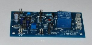
Attachments
Well, judging by the torrid rate of posts there is not all that much interest in this type of relay control circuit. It uses parts that I have on hand, in spades, so for me it's pretty useful.
Unfortunately I just discovered one problem: it can't actually be daisy chained as-is, by connecting the "555 OUT" output of one board to the "EXT TRIGGER" input of the next board. The problem is that the 555 timer begins the delay-on period (e.g. is "triggered") when its input signal goes high, but the "555 OUT" is connected to pin 3, which is already high at power up and goes LOW when the relay state changes.
What I need is a logic inverter, for example using a transistor. Luckily I already have a transistor on board, but it is configured as a logic input. I will probably design a "version 2" of the board that gets rid of the logic input and instead uses the transistor and the couple of resistors associated with it as a logic inverter and then route that signal off board in place of the "555 OUT", or possibly in addition to it. In this way I am just using the PCB real-estate for a different purpose.
In the meantime I can use the existing version 1 board as is and instead of daisy-chaining boards I will just trigger them independently.
I have that exact one, works ok, except sometimes the standby button doesn't turn it off, always turns it on, so not too much of an issue. Thanks for the schematic 🙂
Chinese Soft Start
A dual LED needs to be connected to it to work properly. If one Led is attached (for example the one with built-in in power buttons), it requires two clicks of button to power up.
A dual LED needs to be connected to it to work properly. If one Led is attached (for example the one with built-in in power buttons), it requires two clicks of button to power up.
That's useful info, thanks. At the moment I'm using the dual LED that came with it, but was planning to eventually use one of the power buttons you describe
The use of two sets of two NTC thermistors IN PARALLEL in that circuit is not a good idea, unless they intentionally want two of them to be more or less useless, or only for "backup" in case a thermistor burns up. When you have two NTC thermistors in parallel, as soon as one gets a little more current it's resistance will drop faster than the other and heat up faster and the resistance will go down even more. Soon only one will be carrying almost all of the current. NTC thermistors for a soft-start application like this should only be wired in series because current will not be shared equally among all four thermistors. At least there are effectively two in series...
Otherwise it seems to have some similarities to what I have done, but without some extra stuff that makes my board more versatile.
Otherwise it seems to have some similarities to what I have done, but without some extra stuff that makes my board more versatile.
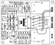
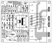
I finished "Version 2" of this board and will probable send it off to the PCB fab tomorrow. Pic of layout attached. I made a couple of changes and simplifications.
I eliminated the "logic input" and converted the transistor and its associated components into a logic inverter. Here's how that is useful: the 555 pin 3 output goes LOW when it energized the relay coil. But the trigger for the 555 needs an input that goes HIGH when you want to start the delay-on period. The logic inverter converts LOW-->HIGH so now I have an output that is LOW when the relay coil is not energized and HIGH when the coil is energized. I now call this the relay state and bring it out to the edge of the board at header "RLY STATE". Directly across the board (up, at top) from this is the external trigger input. This allows the user to place boards side-by-side and simple connect the relay state output of one board to the external trigger of the next board, making them operate one after the other (serially). This is what I had originally intended for the design.
I also eliminated one of the two RC timing capacitors and the ability to switch between "short" and "long" times by jumping a header. You can still get lots of adjustability using the trimpot, or simply populate a resistor instead of the trimpot if you know what delay you would like to use.
Most other functionality is retained e.g. the constant current operation. I did some minor rearranging of components and explicitly brought out the 555's "PIN 3" output. This output, as well as the relay state output, can be used to drive an LED+LDR (e.g. Vactrol) that can be added to the input network of the amplifier to mute the audio input until the relay has triggered, e.g. when it is also connecting the amp to speakers.
The only think left to do is tweak the mounting hole spacing so that it can be mounted on the baseplate of a DIYaudio chassis.
I'm going to be building a couple of amps soon and I think this board will come in very handy for startup sequencing tasks.
Attachments

Last edited:
True, I can't think of a good reason they do it like that. You can only really count on it being the equivalent of two in seriesThe use of two sets of two NTC thermistors IN PARALLEL in that circuit is not a good idea, unless they intentionally want two of them to be more or less useless, or only for "backup" in case a thermistor burns up. When you have two NTC thermistors in parallel, as soon as one gets a little more current it's resistance will drop faster than the other and heat up faster and the resistance will go down even more. Soon only one will be carrying almost all of the current. NTC thermistors for a soft-start application like this should only be wired in series because current will not be shared equally among all four thermistors. At least there are effectively two in series...
Otherwise it seems to have some similarities to what I have done, but without some extra stuff that makes my board more versatile.
- Status
- Not open for further replies.
- Home
- Amplifiers
- Power Supplies
- a versatile delay-on relay board