Very often, one needs a purely static bias voltage: the voltage just needs to be present, but there is no, or negligible current drain.
Think of condenser mics, tube electrodes, varicaps, APD's, etc. for example.
Many solutions exist, but among the preferred ones are voltage-multipliers.
It is well-known that the number of diodes dictates the multiplication ratio.
A quadrupler for example would require four diodes.
But is it really the case?
Here is a challenge to the common wisdom:
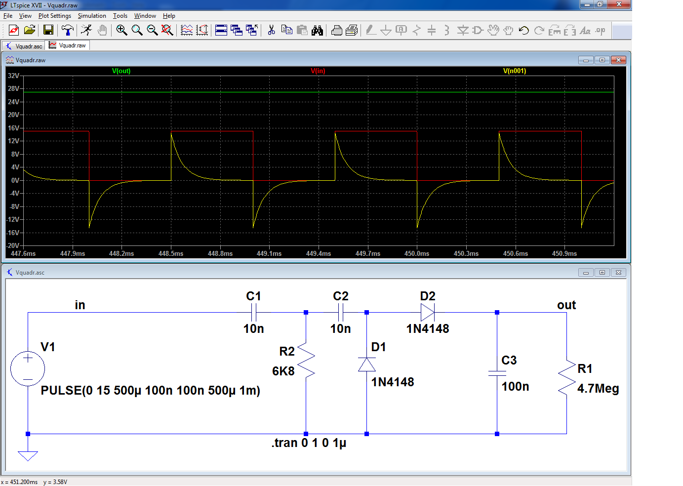
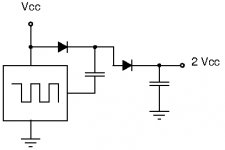
This quadrupler ~quadruples the input voltage, but it does so with only two diodes, plus a magic component.
Here is the circuit without the magic component: it is just a plain vanilla doubler, with the input cap split into C1 and C2, which changes nothing to the way it operates.
A 1kHz, 15Vpp squarewave is converted to a ~15VDC voltage
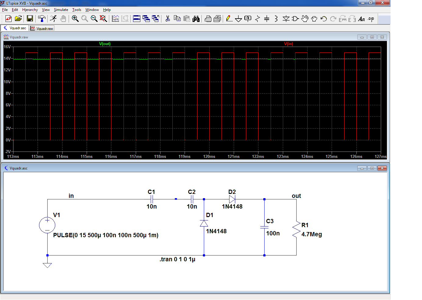
Input and output voltages are perfectly coherent.
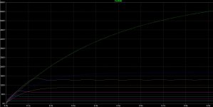
Now, add the magic component (red question mark): the output voltage is effectively quadrupled.
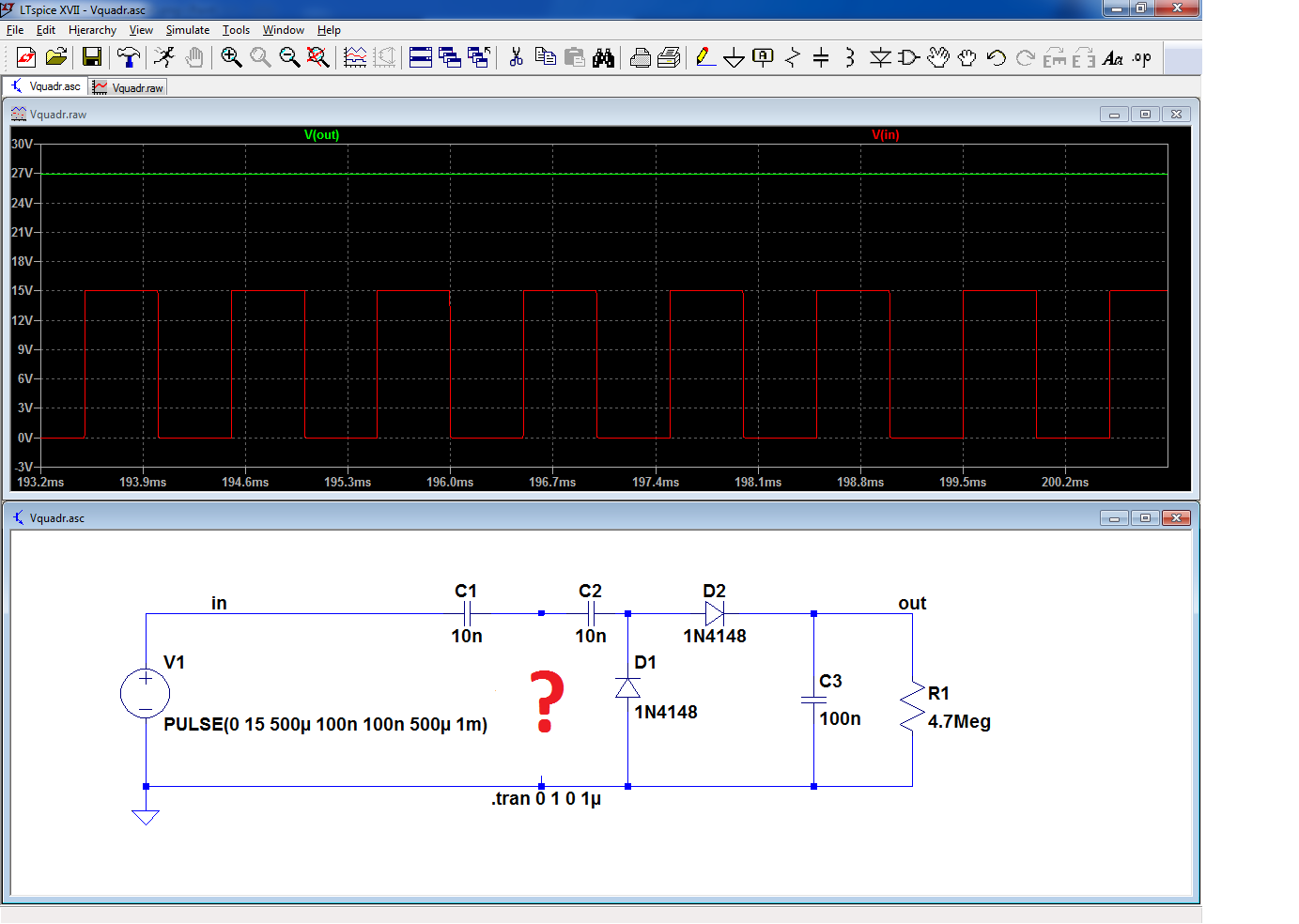
Can you guess what this miracle component is?
Hint: it is nothing complex or fancy, certainly not a resonator or even an inductor, simply one of most basic dipole possible...
I will give the answer in my next post, since the forum doesn't seem to offer the spoiling option..
Think of condenser mics, tube electrodes, varicaps, APD's, etc. for example.
Many solutions exist, but among the preferred ones are voltage-multipliers.
It is well-known that the number of diodes dictates the multiplication ratio.
A quadrupler for example would require four diodes.
But is it really the case?
Here is a challenge to the common wisdom:
This quadrupler ~quadruples the input voltage, but it does so with only two diodes, plus a magic component.
Here is the circuit without the magic component: it is just a plain vanilla doubler, with the input cap split into C1 and C2, which changes nothing to the way it operates.
A 1kHz, 15Vpp squarewave is converted to a ~15VDC voltage
Input and output voltages are perfectly coherent.
Now, add the magic component (red question mark): the output voltage is effectively quadrupled.
Can you guess what this miracle component is?
Hint: it is nothing complex or fancy, certainly not a resonator or even an inductor, simply one of most basic dipole possible...
I will give the answer in my next post, since the forum doesn't seem to offer the spoiling option..
Attachments
Elvee, where do you get all these (good) ideas from? Is it the superior Belgian beer? The rich Belgian chocolate? The Belgian "frites"?, or simply the tobacco you fetch over the border in the north?
What about a diac as the miracle component?
What about a diac as the miracle component?
...not a resonator or even an inductor...
Perhaps a choke...?
A choke is an inductor?
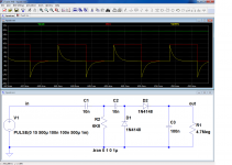
The obvious suspect is a resistor.
(My source is a Sin clipped to a pulse.) (100Meg suppresses a fussy sim complaint.)
Attachments
Last edited:
Right you are. With an RC time constant (much) less than a half-period of the square-wave, the first capacitor will charge the second capacitor with "spikes".The obvious suspect is a resistor.
A diac should work as well but has start-up issues.
PRR got it right of course: it is just a humble resistor
Of course, an inductor works too, as would more complex reactive circuits, which is why I excluded them upfront
When properly differentiated, the 15Vpp becomes 30Vpp.
I found it interesting and paradoxal that adding a parallel damping component in the path of a signal manages to "increase" it.
Of course, you cannot extract lots of power from this oddity, but it could still be useful and spare a pair of diodes
Attachments
It was an interesting quest.
One thing I do not understand is why it is called a voltage quadrupler when it only doubles the voltage swing of the AC signal. For many years the appended voltage doubler design has been the standard and seems to do the same with two diodes and two capacitors, operating with high efficiency.
One thing I do not understand is why it is called a voltage quadrupler when it only doubles the voltage swing of the AC signal. For many years the appended voltage doubler design has been the standard and seems to do the same with two diodes and two capacitors, operating with high efficiency.
Attachments
Last edited:
Historically, voltage multipliers were used with pure AC sources (mainly sinewaves, but not always).
Anyway, the average voltage was always zero (transformers, alternators).
This means that the significant parameter, when averaged over a significant number of stages, is the peak to peak voltage halved and the reference voltage (the "foot" of the multiplier) is zero.
Nowadays, when the AC source is a logic gate, we can chose to reference the diode string to Vdd or Vcc, but this option didn't exist in the early 20th century, when these topologies were devised.
It might also seem that asymetrical waveforms could be an exception, but this exception vanishes as soon as the threshold of 2 (a simple doubler) is reached.
Note that if you reference the quadrupler to the +15V supply, you will get 45V minus the losses... a voltage tripler?
This way of thinking doesn't work if you need a negative voltage: according to the usual classification, the quadrupler will work equally well for positive or negative voltages wrt. ground, but the additional help of the +rail won't be present for "enhanced" multipliers having a negative ground.
The traditional way of classifying voltage multipliers is certainly not perfect, but at least it is not too much context-dependent
- Status
- Not open for further replies.
- Home
- Amplifiers
- Power Supplies
- A two-diode voltage quadrupler