Excellent point Andrew. Would you like to be my publicist? 😀
FWIW even with this firmware "feature" you will still get the entire range of 128 steps from -63.5db to 0 db. The problem is an accumulator overflow that causes an averaging division to go beyond 8bits. So while you don't get full pot travel, you will still get the full attenuator range.

Cheers!
Russ
FWIW even with this firmware "feature" you will still get the entire range of 128 steps from -63.5db to 0 db. The problem is an accumulator overflow that causes an averaging division to go beyond 8bits. So while you don't get full pot travel, you will still get the full attenuator range.
Cheers!
Russ
Russ White said:FWIW even with this firmware "feature" you will still get the entire range of 128 steps from -63.5db to 0 db. The problem is an accumulator overflow that causes an averaging division to go beyond 8bits. So while you don't get full pot travel, you will still get the full attenuator range.
Hi Russ,
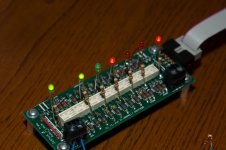
I’ve soldered some led’s to the relays, to visualize the relay settings, (it looks ugly but it is very efficient).
And indeed Russ, after all the 128 steps (all relays on), it start all over again. (14 steps to be precise, to full pot travel).
Because you get al the 128 steps, not a real problem. But should if you have plans to fix it, I would like to trade my PIC.
Gr, Bastiaan
Attachments
Thanks Blimp, that confirms exactly what I was thinking.
And hey it looks cool too. 😀
I will get a chance this evening to adjust the firmware. We will work with those of you who want replacement firmware. Thanks so much for the good will and help in tracking this down.
Cheers!
Russ
And hey it looks cool too. 😀
I will get a chance this evening to adjust the firmware. We will work with those of you who want replacement firmware. Thanks so much for the good will and help in tracking this down.
Cheers!
Russ
The Jt firmware is corrected. There appears to be a compiler issue with division of unsigned chars. In any case, it is fixed now and we will send new firmware to people who have purchased JTs already and want it. The 1.1 firmware will work fine, it just has the "don't turn that knob all the way" protection feature built in. 🙂
Cheers!
Russ
Cheers!
Russ
Interesting concept
I planned on building my JT kit as a conventional separately housed passive attenuator feeding monoblock RevC amps, but the more I think about it, I wonder if an unconventional configuration might be better.
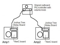
What do you guys think of putting a separate JT relay board in each of the monoblock amps fed by a shared controller board in a separate chassis?
The line level source would plug directly into each amplifier. The nice thing about this setup is that there are fewer connections/interconnects in the audio signal path. See my diagram. There would be only one source in my setup, so I don't need source selection.
I planned on building my JT kit as a conventional separately housed passive attenuator feeding monoblock RevC amps, but the more I think about it, I wonder if an unconventional configuration might be better.
What do you guys think of putting a separate JT relay board in each of the monoblock amps fed by a shared controller board in a separate chassis?
The line level source would plug directly into each amplifier. The nice thing about this setup is that there are fewer connections/interconnects in the audio signal path. See my diagram. There would be only one source in my setup, so I don't need source selection.
Attachments
Its interesting allright, but its also very locked up. For flexibility its better to have a dedicated preamp, active or passiv. You might want to build another poweramp someday, or go active in the preamp stage.. there is lots of possibities where you are better of with dedicated units🙂 Your proposed setup, will have you rebuild everything, if you want changes. If you are into DIY, you will🙂 So I think that you are better of, building a dedicated preamp. (Just in case you didnt guess that allready😀 )Interesting concept
Steen😎
Hi Carl,
There is absolutely no reason what you propose would not give you excellent results.
The RevC does great with just an attenuator on the front, and if you want an integrated amp, instead of a seperate preamp you will indeed have good results.
I have done the same as you propose except everything was in one chassis. Two complete amps and one JT controller with two relay boards. I was very happy with the result.
But, Steen's point about flexibility with a standalone preamp is a good one.
Cheers!
Russ
Hi Russ
Where can I find the the resistor calculator. I have an extra set of boards and thought I might play with some different values then the kit. I built the kit up and listened to it this morning. Sounds really nice. I have it connected to a diy Millet Hybred headphone amp the called for a 50k pot. I don't get to a listening volume until about 1/2 way up on the pot. So I am looking to match the JT a liitle better with different resistors. I am still trying to wrap my mind around the necessary match between amp and attenuator. Any education would be welcomed.
Thanks
Jim
Any update on remote control?
Does anyone have thoughts on how to make the JT remote controlled?
Thanks
Does anyone have thoughts on how to make the JT remote controlled?
Thanks
One is definitely in the works. But it will likely not be very soon coming, I am just now closing on my old home, and will be moving over the next couple weeks, then I will need to get my new workshop in working order so I can begin working on my hobbies again. 🙂
Thoughts?
Here's one thought...
Does anyone have thoughts on how to make the JT remote controlled?
Here's one thought...
An externally hosted image should be here but it was not working when we last tested it.
An externally hosted image should be here but it was not working when we last tested it.
Russ, you da man. Good luck with your transition into your new home. Do you envision encorporating a Darwin selector into your remote control too?
Brian, very cool. That's a lot more than one thought. Is that remote device available for purchase? Or at least the board/chips? Nice work.
Brian, very cool. That's a lot more than one thought. Is that remote device available for purchase? Or at least the board/chips? Nice work.

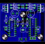
It's just a prototype I made up... quick and dirty. It uses a Rentron Sony RC5 decoder chip and a quad half-bridge to drive the motor. The motorized pot I got surplus, super cheap, but works. It would be fine with a single 5V VReg, but I am thinking it should use a LM317 for the motor voltage, adjustable, to customize speed. I initially used 12V, but speed made it too sensitive.
Well, I put a rectifier on the board too so you could tap right off the trafo. I will test it with the JT trafo and balanced JT, but I shoudl be fine. When the motor is at full rotation and the clutch is slipping, it was only drawing 65mA at 12V. Need to check at 5V, but would guess it would be about 150-200mA or so. Shoudl be okay.
Attachments
orthoefer said:Russ, you da man. Good luck with your transition into your new home. Do you envision encorporating a Darwin selector into your remote control too?
Brian, very cool. That's a lot more than one thought. Is that remote device available for purchase? Or at least the board/chips? Nice work.
Yes definitely. Brian and I call it the "Uber Controller" because it will control JT,Darwin, and possibly even Kooka, and who knows what else. 🙂
 Nice!
Nice! 
- Status
- Not open for further replies.
- Home
- Design & Build
- Parts
- A twisted tale about a logarithmic relay attenuator