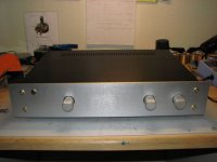
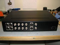
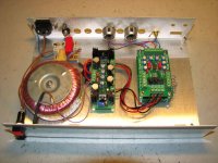
Now that I am at it anyways, I also made the Opus DAC which was just "kind of" finished today. Since I havent decided whether I want a seperate DAC or build it into the CD player yet, its just build into a network box that was lying around.
How it sounds? Simply wonderful🙂
Steen🙂
How it sounds? Simply wonderful🙂
Steen🙂
Attachments
Pretty cool Steen!
Why dont ya stick the DAC right in the pre. You certainly have room! Wow that stuff is small.
Your right - The Joshua Tree is very slick😉
Why dont ya stick the DAC right in the pre. You certainly have room!
Wow that stuff is small.Your right - The Joshua Tree is very slick😉
Zen Mod said:ugly!

Agree😀 I am looking forward to compare this preamp to a Pumpkin😉
mpmarino said:Pretty cool Steen!
Why dont ya stick the DAC right in the pre. You certainly have room!
Your right - The Joshua Tree is very slick😉
Thanks. Yeah I might build it into the pre, thats what Russ suggested too. Somehow I find it misplaced in the pre, but I am probably just being oldfashioned.
🙂
Russ White said:We are currently using and planning for a 20 x 2 PLED. It works just like an LCD display but is much brighter and easy to read. It looks a lot like a VFD display but is much more reasonably priced.
hmm looks like pled/oled no longer available

http://www.matrixorbital.ca/Members/Nick/pled
http://www.crystalfontz.com/products/index-pled.html
I'm just curious what the current version of the joshua tree's impedances are.... I was attempting to read through all the posts but I'm at work....and probably should be working...
looking for:
range on input impedances
output impedance
was thinking of driving it with an aikido (6BL7 outputs), but that will depend the input and output impedances...
thanks
looking for:
range on input impedances
output impedance
was thinking of driving it with an aikido (6BL7 outputs), but that will depend the input and output impedances...
thanks
Boris_The_Blade said:I'm just curious what the current version of the joshua tree's impedances are.... I was attempting to read through all the posts but I'm at work....and probably should be working...
looking for:
range on input impedances
output impedance
was thinking of driving it with an aikido (6BL7 outputs), but that will depend the input and output impedances...
thanks
Hello,
Input impedance ranges from approximately 2.2K to 10K (pretty easy load for a source like the Opus).
The output impedance is 750R.
Cheers!
Russ
Cobra2 said:Which makes it almost useless for a tube-dac/riaa/... ?
Arne K
Maybe, but why exactly?
If it's because of a high source impedance you could add a buffer in front of the JT.
Also its very very easy to calculate higher values (at the expense of higher output impedance).
Cheers!
Russ
Russ White said:
Hello,
Input impedance ranges from approximately 2.2K to 10K (pretty easy load for a source like the Opus).
The output impedance is 750R.
Cheers!
Russ
Russ White said:
Maybe, but why exactly?
If it's because of a high source impedance you could add a buffer in front of the JT.
Also its very very easy to calculate higher values (at the expense of higher output impedance).
Cheers!
Russ
Many commercial units have higher output impedance than that...
-it should have been mentioned in the documentation.
And, if we can order a alternative, that should be mentioned also 😉
AND you still have firmware v.1,1 on yourweb. V.1,2 is only listed in this tread!

Arne K
Cobra2 said:
Many commercial units have higher output impedance than that...
-it should have been mentioned in the documentation.
Arne K
You are at this moment reading the documentation. 😉
Why would you expect any attenuator to work for all sources? You can't use a 5K pot where a 50K is required. All this has been mentions numerous times. This is DIY, all the documentation you need is right here.

If you have an output impedance > 1K then you will need to calculate new resistor values. Its not hard. Even easier use a simple buffer. That would actually very likely sound better.
The "stock" resistor values and the method to generate your own values are both documented quite well in this thread. At some point you have to take responsibility to do a little research.

I am not sure what your point is about the firmware versions. I believe I have posted all of theme here, and the newest version always comes with the kit. If the website mentions an older version, we will correct that.
Cheers!
Russ
I haven't read through this thread yet (though I did search through it), but I have a question. I have the boards populated and only need to put the connectors onto the cable. I'm feeling somewhat like an idiot because I'm not sure how to do it. I've tried applying pressure to jam the pins into the wire, but I'm starting to suspect I'd need a hammer to make any headway. Do the wires need to be seperated and stripped?
The wire's do not need to be stripped or separated, it just take some pressure. The pins will cut the edges of each wire's insulation and crimp around the copper.
You want to apply a smooth, even pressure. The easiest way is to use a vice. If you don't have one handy, try some large pliers: squeeze one end partially, then the other end, then in the middle. Then back at the first end, sueeze it all the way, then the other end, then the middle.
Be sure you get the cable orientation right by aligning the red wire with the arrow on the connector (pin 1).
The little piece that goes on the back of the connector is a strain relief. You can loop something through it to tug on when you want to disconnect the connector, without having to pull on the cable.
Sheesh, I'm such a moron, haha. I deal with termination methods pretty similar to this at work, so it shouldn't have been too difficult. After your post I went and got the connectors on in about 2 minutes 🙄
I have a small problem, though. When I power up, the relays just keep clicking...any ideas?
-EDIT- ok, I just took a look at it again. If I turn the pot, the clicking accelerates over a small part of the range and stops everywhere else. I have it hooked in an amp, and using a pair of test headphones it's passing along the input signal to the amp. If I have the headphones on and go through the region where the clicks accelerate, the volume will go up or down (depending on which direction I'm turning) and as soon as I get out of that region, the volume stays constant. Could this be an issue with the pot or the PGA?
Did you find the problem? I was going to ask if you added the jumper to the bottom of the controller board.
I haven't found the problem yet, but I haven't had much time to look at it yet. I did add the jumper on the controller board.
Further clarification on the behaviour I'm experiencing: the first ~60% of the pots range doesn't do anything (stays constant), from maybe 60-75% the volume sounds like it's trying to increase then resets back to a lower level, and around 80-85 I get a steady increase in volume until I turn it away from that point. Anything past 85-90% on the pot just maintains whatever volume it's at.
I'm going to do some other checks in a bit, but one I've checked is that the regulated 5v stays constant and doesn't dip anywhere in the pot's travel.
- Status
- Not open for further replies.
- Home
- Design & Build
- Parts
- A twisted tale about a logarithmic relay attenuator