You are most welcome! BTW if you can't locate a schem of the original version of it..send me a message through DIYA. It may give you some ideas towards doing your own. Basically they use an non-inverting op amp gain stage at the input followed by two j291 jfet common source stages, a tone network then a buffer (j291 source follower) output. My perfboard project used a mosfet stage as the input, driving two jfet stages. I was going to start putting a tone network in, just got distracted by many other projects since! CheersThanks for the tip! I found one video of it that sounded pretty good
Interesting design indeed, I would also suggest to check the G.I.V.E. circuit in Gallien Krueger 1001RBII. Not the one in 1001RB, that is just two zeners to cut signal, but the II, that has a fet (IIRC J201 supplied with +15 and -48V) just before the power amp.
In its simplicity, I've always found it very musical and dynamic.
It is for sure needed to know how they selected the fets for mass production in such a "sensitive" working condition.
In its simplicity, I've always found it very musical and dynamic.
It is for sure needed to know how they selected the fets for mass production in such a "sensitive" working condition.
The crossover to mass production from DIY one-off project is a bit more of a challenge with FETs. But for hand assembled "small batch" electronics it's not too difficult.It is for sure needed to know how they selected the fets for mass production in such a "sensitive" working condition.
Japanese companies such as Roland, , having local suppliers and being important customers, always had the luxury of buying products preselected at the factory.
Not only Fets but bipolars too.
Notice schematics often specify "2Sxxx"(G) or (Y) (green or yellow or whatever colour) meaning fully finished, encapsulated and marked transistors were tested one by one then being marked by an extra colour dot.
That certainly makes (large) manufacturer´s life easier.
Maybe not in that year/version but Fet based GIVE technology was a common feature of thousands of G&K amplifiers.I looked at Gallien Krueger 1001RBII service manual, the 32 page version and there is not a j201.
Is it possibly another unit?
jfetter, that service manual is only for the poweramp, not the preamp.
I remember the one I tried it is different, but check this:
GK 400 RB circuito.pdf
over there is a J113 supplied by dual 15V (bit less, due to the 4k7 and Ids), with 12k on drain and 33k on source, with a partial bypass. IIRC I tried another version with 47k on source but don't remember other details.
This is from a '92 GK400RB head.
When driven hard, FET gate gets positive on signal peaks , rectifies, shifts bias so shifts duty cycle, transconductance, gain, etc.
A "poor man´s tube" equivalent with nice grungy tone; absolutely different to cheap diode clipping used in later versions.
When driven hard, FET gate gets positive on signal peaks , rectifies, shifts bias so shifts duty cycle, transconductance, gain, etc.
A "poor man´s tube" equivalent with nice grungy tone; absolutely different to cheap diode clipping used in later versions.
Attachments
Thanks for the explanation JMFahey, it is very grungy and tubeish indeed, but I've never used it with a guitar, only bass. How does it sound with guitar? It would benice to try multiple stages in series, less pushed.
That's certainly a valid approach, too....however a 12AX7 or 6922 cost a few bucks each and can be used to provide the tube sound to SS amplifiers.
I can't find any cheap 12AX7s where I live (they're $30 or more in local music shops, for instance). But the 6N2P (12AX7 equivalent) can be sourced from former Soviet-bloc countries for a few bucks.
Many of us have had the idea of using a BJT or power MOSFET to "boost" the current from a small-signal tube, but most attempts end up with fried semiconductor devices. 🙂A 12AX7 and 6922 pure triode output section with MJE13007 current boost provides 30w from a 150v B+.
If you found a way to make it work, I would love to see your schematic, if you're willing to share.
-Gnobuddy
Just breadboard and try a couple stages 🙂Thanks for the explanation JMFahey, it is very grungy and tubeish indeed, but I've never used it with a guitar, only bass. How does it sound with guitar? It would benice to try multiple stages in series, less pushed.
To avoid starting from zero I´d build a simple transistor amp channel, say Peavey/Laney/Fender/Marshall from their beginner/entry level line (which are simple but not really bad, at least for clean sound) and replace the typical harsh diode or red led clipping by these GIVE type stages at the end , and then send that straight to power amp through a pot which becomes amp "Master".
So you avoid diode clipping of any kind and overdrive a "similar to tubes" gain stage instead.
Basically what they do in the Bass amps.
Not sure about heavy metal high gain sounds, but you should approach classic Fender amp played loud sound.
i have used current boosted tubes for years mostly with power fets and bjt.
but now using opamps.
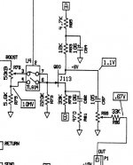
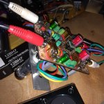
This circuit works 100% perfect. was listening a few minutes ago.
you really only need the first stage , i put a makeup/headphone opamp stage here for connivence in case tone volume used.
u can roll with pentodes too by using screen as plate.
The output is the error signal from opamp driving to tube to linear.
but the linear output is discarded leaving that wonderful tuby sound.
every tube type has its own sound that you can see in fft plots.
30v potential works fine. (+-15v)
Very low current is used so bias is always negative with no positive grid.
The 12BH7 is my favorite sounding so far. I use 700ua.
Clipping is a different story so this is not for effects box etc.
but now using opamps.
This circuit works 100% perfect. was listening a few minutes ago.
you really only need the first stage , i put a makeup/headphone opamp stage here for connivence in case tone volume used.
u can roll with pentodes too by using screen as plate.
The output is the error signal from opamp driving to tube to linear.
but the linear output is discarded leaving that wonderful tuby sound.
every tube type has its own sound that you can see in fft plots.
30v potential works fine. (+-15v)
Very low current is used so bias is always negative with no positive grid.
The 12BH7 is my favorite sounding so far. I use 700ua.
Clipping is a different story so this is not for effects box etc.
Attachments
Thank you for your circuit!Jfetter said:i have used current boosted tubes for years mostly with power fets and bjt.
Stocktrader200 referred to using a 12AX7 and an MJE13007 to get about 30 watts output power from a 150V power supply, which suggests about a half-ampere of peak output current, and an output transformer to step down from roughly 300 ohms impedance to the 8 ohm or 4 ohm speaker impedance.
Since it is hard to get much more than a milliamp out of a 12AX7, getting to 500 mA peak outut current requires a current gain of several hundred in the semiconductor device. An MJE13007 can have a DC current gain as low as 8 times, which is nowhere near enough. So Stocktrader's circuit must include other elements.
Maybe Stocktrader's circuit is just a Darlington pair emitter follower buffering the triode anode, and a 300 ohm to 8 ohm output transformer. Maybe something else. It would be interesting to know for sure.
Thirty-watt, 300 ohm to 8 ohm output transformers are not the most common devices either. Perhaps Stocktrader is using a hefty audio line output transformer. It would be nice to know.
Incidentally, I don't think there is any fundamental difference between having a unity-gain solid-state buffer operate at the full 150-volt tube supply, and making the circuit simpler by dividing down the tube output signal to, say, line level, and using that to drive a contemporary class-D power amplifier module. The latter approach avoids the need for the 30-watt output transformer.
-Gnobuddy
I've never used a 12ax7 in current boosted.
6sn7, 6sq7, 12au7, 6v6, el84, 6l6, 6n13s-6as7 and the Raytheon micro tubes Yes.
Paralleling twin triodes works great too if driving IGBTs or low gain bjt in discrete CFP Sziklai boosted.
For those I used +-24v. Schematics are put up on diyaudio but difficult to find.
The sziklai is normally operated open loop so clipping would be interesting.
I have not explored it throughly.
cheers.
Sorry if too much off topic.
Attachments
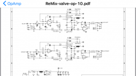
I use a circuit very similar to this to add a nice soft overdrive to a Hammond clonewheel (Nord C2D). The circuit can be driven hard but I never use it like that. Rather, just enough overdrive to make it less sterile through a solid-state Leslie.
I followed the design of a circuit that was recommended to me by a user on diystomboxes.com. It was used as a way to turn triangle waves in to sine waves for synthesizers. See the 4th schematic in A Study of Sub-Oscillators (and Oscillator Waveshaping). He also references Tim Stinchcome's website which discusses the ovedriven differential pair approach and contains a number of journal references discussing it.
I followed the design of a circuit that was recommended to me by a user on diystomboxes.com. It was used as a way to turn triangle waves in to sine waves for synthesizers. See the 4th schematic in A Study of Sub-Oscillators (and Oscillator Waveshaping). He also references Tim Stinchcome's website which discusses the ovedriven differential pair approach and contains a number of journal references discussing it.
Btw, this is an old idea of mine dating back to the 70s or 80s. At that time I discovered in an RCA data book CA3080 where the scope plot of the s-shaped transfer function had been depicted. It made "click" and immediately I saw the solution for a smooth distorting unit better than si-diodes or ge-diodes. I used these transconductional operational amplifiers (OTAs) over decades until they went obsolete. Breaking down its intrinsic circuitry it is just a differential amplifier feeding current mirrors that can be emulated with few discrete off-the-shelf components.
And as a benefit the access to emitter degeneration adds the option of asymmetric distortion.
Hello,
I tryed the simulation.
If input is 100mV. it work great but for the other values such as 500mv, 1v or so... The output sinus wave has flat top.
What i need to modify to make it work as expected in different input amplitude.
Attachments
- Home
- Live Sound
- Instruments and Amps
- A "tubey" solid-state soft limiter