Suppose a dome midrange driver has a natural roll-off frequency of 540 Hz with a 12 dB/octave slope rate.
Can we establish a higher-order slope by adding a passive (or active) crossover of the same corner frequency and same slope, i.e., 540 Hz @ 12 dB/octave, to this driver?
Will we obtain a new slope for this driver at 540 Hz with 24 dB per octave?
Can we establish a higher-order slope by adding a passive (or active) crossover of the same corner frequency and same slope, i.e., 540 Hz @ 12 dB/octave, to this driver?
Will we obtain a new slope for this driver at 540 Hz with 24 dB per octave?
Yes. If both the filter and the driver have a Q of 1/2 √2, the combined response will be fourth-order Linkwitz-Riley with a -6.02 dB point of 540 Hz.
The question is how well the driver can handle signals at 540 Hz. It may not be very good at that if it is meant to be crossed over much higher than 540 Hz.
The question is how well the driver can handle signals at 540 Hz. It may not be very good at that if it is meant to be crossed over much higher than 540 Hz.

Actually, this is my idea to do an experiment on my speakers, the ADS L1590/2.
They are equipped with a 2" midrange dome, and their passive high-pass filter for the midrange is composed of 32 uF and 2.6 mH. From the online calculator, the result is that the crossover is set at approximately 540 Hz with a 12 dB/octave slope.
My idea is to try to convert it to a 4th-order slope with the same corner frequency by using an active crossover. So, to my understanding, I should set the slope rate on my active crossover to 12 dB/octave, shouldn't I?
Yes, as long as you can verify the result. It may not have a 12dB slope now, and as Marcel says you’ll need to adjust the Q.
I think what Marcel meant is that it is not a good idea to use a driver all the way down to its natural roll-off frequency.
It will start to seriously distort and breakup before that.
Rule of thumb is that you should stay away at least an octave from that point.
As an example, a driver that naturally rolls off at 540 Hz not be used below 1080 Hz.
Jan
It will start to seriously distort and breakup before that.
Rule of thumb is that you should stay away at least an octave from that point.
As an example, a driver that naturally rolls off at 540 Hz not be used below 1080 Hz.
Jan
I got it. But, actually, these drivers were designed to have an electrical response (the passive crossover's response) with the corner frequency at approx. 540 Hz @ 12dB/octave from the factory. So, I believe converting it to fourth-order with the same corner frequency make them play safer.Rule of thumb is that you should stay away at least an octve from that point.
As an example, a driver that roll off at 540 Hz not be used below 1080 Hz.
I'm a bit hesitant now.
The midranges have passive crossovers employed at 540 Hz @ 12 dB/octave. And the active crossover can be switched between 12 and 24 dB/octave operations. My goal is to realign the acoustic response of the midranges from 2nd to 4th order with the original corner frequency.
In order to achieve the goal, can I simply set the active crossover to operate in the 24 dB/octave mode without paying attention to the passive crossover? Or do I need to set the active crossover to operate in the 12 dB/octave mode because attention needs to be paid to the passive crossover?
Last edited:
Both roll-off's will combine, so the passive and active crossover will work together to create the new roll-off. What we didn't consider yet is the roll-off of the driver itself.
You mention you've calculated the passive components to introduce a second order at 540 Hz. Did you use the nominal impedance of the driver in the crossover calculator to come to that conclusion (for instance 8 ohm)? Or did you use the impedance curve of the driver in the enclosure.
What is the roll-off of the driver itself? At what frequency does it have an impedance peak? How close is the crossover to that impedance peak of the driver itself? All these things matter to get the right values.
Easiest would be to measure the driver with it's passive crossover to see if it really does have a second order roll-of at ~540 Hz.
In any case, active crossover at 12 dB/octave will be closer to the target than 24 dB/octave. (The acoustical roll-off can only make it steeper.)
In most cases text book filter slopes combined with real drivers will yield sub-optimal results: the filter transfer function and the drivers' need to be optimized (read: tailored or optimized) to achieve a textbook e.g. 4th order final acoustic roll off. This is what filter simulators that are based on import of driver measurements (.frd or .txt and .zma files) have done for decades now. KEF showed the way as early as 1978.
Attachments

They are equipped with a 2" midrange dome, and their passive high-pass filter for the midrange is composed of 32 uF and 2.6 mH.
It already has a passive crossover, but what is the roll-off of the driver itself and how do the passive components react to the driver's impedance.
wesayso
I didn't use the driver's impedance in calculation. I just focused only on the electrical response of the active crossover, since I run the system in active, the bi-amplification.And the passive crossover of the woofers has simply two components containing a capacitor and an inductor to form a basic second-order filter.
Therefore, I just duplicate the electrical response of the passive crossovers.
The midrange dome has a passive crossover on it, right? Those passive components will react to the impedance curve of the driver, not the nominal impedance. Say at ~500 Hz the impedance cuve of the driver shows a value of 6 ohm instead of it's nominal 8 ohm value as noted on the spec sheet, the true crossover will differ from what you calculated.
(Edit ^^^) Not necessarily. The closest thing to a proper 12dB filter you have without measuring yourself, is the passive crossover.. assuming you leave it there. It could be assumed to be compensating for the driver to some degree whereas the active won't.
I guess this thread is a follow up from this: https://www.diyaudio.com/community/threads/should-i-modify-my-existing-crossovers.400102/
Not 100% related. That thread just talked about passive crossover and about woofers voicing, whereas this thread talked about active system and midrange voicing.I guess this thread is a follow up from this: https://www.diyaudio.com/community/threads/should-i-modify-my-existing-crossovers.400102/
So then you have to combine it with another second-order high-pass to get a fourth-order response, whereas combining it with a fourth-order high-pass will not get close to a fourth-order overall response.(Edit ^^^) Not necessarily. The closest thing to a proper 12dB filter you have without measuring yourself, is the passive crossover.. assuming you leave it there. It could be assumed to be compensating for the driver to some degree whereas the active won't.
@presscot Are you trying to do a simple experiment where you combine the second-order passive crossover with an existing active crossover that can be switched between either 12 dB/octave or 24 dB/octave, trying to get the response of the cascade of both crossovers and the loudspeaker close to 24 dB/octave?
Or are you interested in designing an active crossover that brings the overall response as close as possible to 24 dB/octave? In that case, with or without the passive crossover in the signal path?
In the first case, the answer is simple: set it to 12 dB/octave, 540 Hz to get an overall response close to 24 dB/octave, 540 Hz, although it is a bit unclear how close it will be.
In the other cases, you need to know the details of the driver.
Last edited:
I use this method all the time on the low pass of a woofer to get a steep (close to 4th order) slope using only a 2nd order electrical filter. You need to choose the woofer to have minimal breakup where you want to place the filter. If the woofer is acoustically modified with an enclosure such as a slot loading alignment, the falloff is determined by the depth of the slot and quarterwave theory. For my SLOB bass array with 6.5in drivers, the slots make a 475Hz falloff and I combine that with an electrical filter to get a pretty clean and fast drop. The slot lets you set the acosutic falloff away from the breakup point (if any).
If you look at the XO curves on my 3 way SLOB speake, the woofer falloff here (red response curve - not top average response tilt), the falloff slope from about 400Hz to 800Hz is about -24dB/octave and this was accomplished with a single inductor and capacitor 2nd order electrical filter.

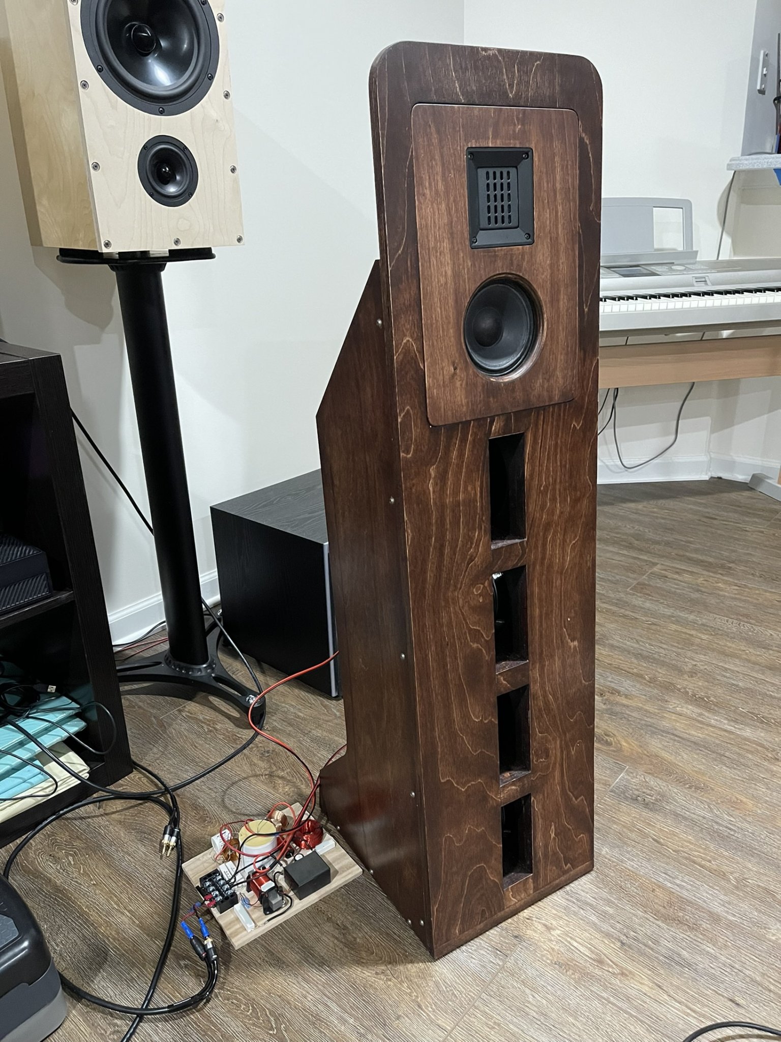
Here is the bass array showing the slots created by 3 sheets of 3/4in MDF stacked with two face sheets to create a slot with a semi circle closed end.
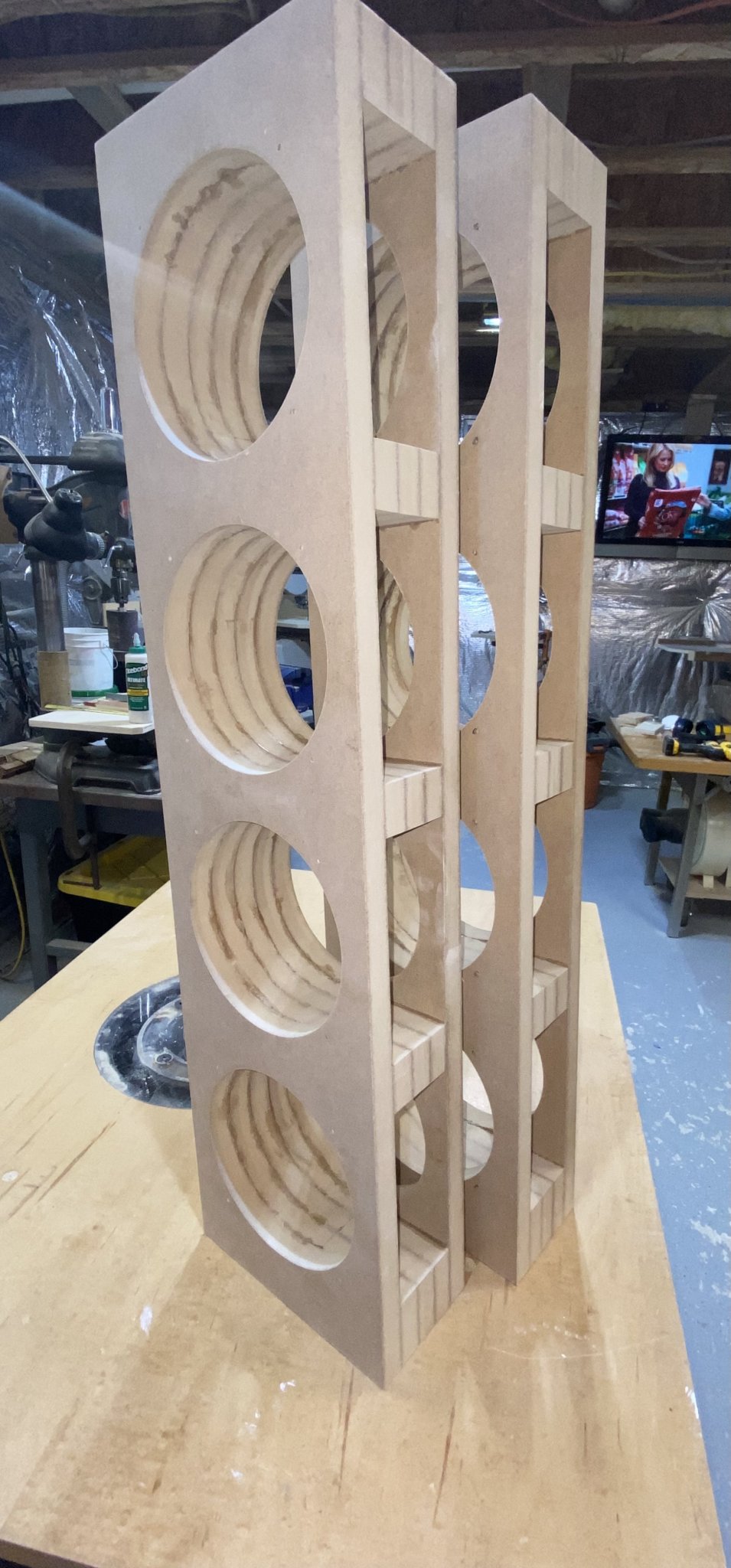
This woofer array box is mounted on a baffle with wings and gets pretty good deep bass with high efficiency for an open baffle as the cone surface area is a bit more than two 12in driver equivalents.
If you look at the XO curves on my 3 way SLOB speake, the woofer falloff here (red response curve - not top average response tilt), the falloff slope from about 400Hz to 800Hz is about -24dB/octave and this was accomplished with a single inductor and capacitor 2nd order electrical filter.
Here is the bass array showing the slots created by 3 sheets of 3/4in MDF stacked with two face sheets to create a slot with a semi circle closed end.
This woofer array box is mounted on a baffle with wings and gets pretty good deep bass with high efficiency for an open baffle as the cone surface area is a bit more than two 12in driver equivalents.
Last edited:
- Home
- Loudspeakers
- Multi-Way
- A trick for creating a higher-order slope