Hello, I'm working around understanding of the transient response of a loudspeaker, and I've learned that a good transient response is equal to a good capability to reproduce correctly a square wave (from this very good article).
Can you help me understand correlations between various filter topologies and their transient reproduction capabilities, related to their phase behaviour?
Does it exist a simulator to study the square wave behaviour of a loudspeaker?
Thank you very much.
Can you help me understand correlations between various filter topologies and their transient reproduction capabilities, related to their phase behaviour?
Does it exist a simulator to study the square wave behaviour of a loudspeaker?
Thank you very much.
Are you familiar with electronic circuit simulators like LTspice? You can model a speaker with L, C, R components and then simulate its behaviour.
Jan
Jan
Unfortunately no, I'm not an engineer and I haven't enough theorical basis to use these programs correctly. Once I've seen somewhere a plot of a transient response made by one of the many loudspeaker design applications, but I don't now what in particular. However it wasn't a square wave behaviour, just the response under the application of an impulse.
It helps to understand, which phase distortion a single analogue filter introduces. For each order of a high- or lowpass, phase turns by Pi/2 altogether, hence a high- or lowpass of fourth order turns phase by 2Pi. The frequency, where phase turn is half of complete phase turn, is a special one, for example cross-over point. Allpasses are an exception in the regard, that they have twice the phase turn per order, say Pi per order.
Cross-overs of odd order are non-correlated, which means, that they do not sum by amplitude (+6dB at crossover point) but by power (+3dB there), and therefore have Pi/2 phase difference between both paths, tilting the beam, unless crossover point is low enuf, or unless this is a symmetrical arrangement as in D'Apollito. A Butterworth crossover of third-order works best with flipped polarity, since it is a combination of a second-order and a first-order crossover. Then, impulse distortion is the same as the one of a second order low- or highpass with Q=1.
Cross-overs of even order are correlated, what means no phase difference.
I believe, that a loudspeaker should have the more phase turn the louder it is. The average for home HiFi should be Pi phase turn between 150 and 7 KHz. I do not believe too much in science and technics.
Last edited:
After the "Transient Perfect" U.S. approach, the "Quasi-Optimum" french school,
with free square wave torture simulator:😛
http://www.acommeaudio.fr/files/filtre_alignement_synthese.xls
These debates were trending topic some years ago, now they are somewhat eclipsed by polar responses, Loudspeaker Gestalt and psychoacustics...😉
http://www.diyaudio.com/forums/multi-way/121175-lecleach-paper-crossovers.html
You need flat phase speaker for transient perfect. Very few examples exist commercially. Dunlavy SC-IV, B&O 45-2 (and similar hole filler XO's), Danley SH-50. Probably a few more but not many.
More info here:
http://www.diyaudio.com/forums/multi-way/88135-filler-driver-ala-b-o.html
Harsch XO:
http://www.diyaudio.com/forums/multi-way/277691-s-harsch-xo.html
Xsim can simulate a transient perfect xo and and show what the transient step response looks like.
More info here:
http://www.diyaudio.com/forums/multi-way/88135-filler-driver-ala-b-o.html
Harsch XO:
http://www.diyaudio.com/forums/multi-way/277691-s-harsch-xo.html
Xsim can simulate a transient perfect xo and and show what the transient step response looks like.
The strait-forward way to impulse-true loudspeakers is the first-order crossover. The use of such filters attracts to a construction, in which the tweeter is of the same size as the woofer(s). Filters of second order attract to a construction, in which the tweeter is twice as small as the woofer. The main mistake of HiFi for the last fifty years were dome tweeters.
The strait-forward way to impulse-true loudspeakers is the first-order crossover. The use of such filters attracts to a construction, in which the tweeter is of the same size as the woofer(s). Filters of second order attract to a construction, in which the tweeter is twice as small as the woofer. The main mistake of HiFi for the last fifty years were dome tweeters.
Despiste pre echo paranoic ghost digital myth busters claims, linear phase fir filters don't bite either. They are my best friends...😎
Hello, I'm working around understanding of the transient response of a loudspeaker, and I've learned that a good transient response is equal to a good capability to reproduce correctly a square wave (from this very good article).
Can you help me understand correlations between various filter topologies and their transient reproduction capabilities, related to their phase behaviour?
Does it exist a simulator to study the square wave behaviour of a loudspeaker?
Thank you very much.
XSim by Bill Waslow will definitely help you. 🙂 It has built in impulse, step and square wave simulations for any given speaker you simulate. Of course, it requires accurate electro-acoustical data to work, but you can use ideal drivers or samples data from Parts Express for any Dayton driver.
Best,
Erik
Hello all, excuse me for the late, I'd want to thank everybody for the ernormous amount of usefulness of the given informations.
@Grasso789:
However, I might deepen the questions regarding correlations between filters topology and phase, I understand that phase is at the center of about behaviour of each loudspeaker component, I have to study more and more..
@GDO:
@eriksquires:
Do you know a faster althernative method..?!
Thank you very much, have good time!
@Grasso789:
For odd order do you intend, for example, an high-pass and a low-pass of different order or an hig-pass and a low-pass of 1st or 3d order?Cross-overs of odd order are non-correlated, which means, that they do not sum by amplitude (+6dB at crossover point) but by power (+3dB there)
Is flipped polarity, in this case, referred only to one of the two way or to both? Why using this method it's obtained a combination of a 2nd order and of a 1st order?A Butterworth crossover of third-order works best with flipped polarity, since it is a combination of a second-order and a first-order crossover. Then, impulse distortion is the same as the one of a second order low- or highpass with Q=1.
Please, can you explain this better to me? Thanks.I believe, that a loudspeaker should have the more phase turn the louder it is
However, I might deepen the questions regarding correlations between filters topology and phase, I understand that phase is at the center of about behaviour of each loudspeaker component, I have to study more and more..
@GDO:
What's these two technologies? Of fir I've already listened but without ever deepen significancy.. do they belong to the digital domain?Despiste pre echo paranoic ghost digital myth busters claims, linear phase fir filters don't bite either.
@eriksquires:
Thank you, very useful application, strong and light. Just two questions: aren't required T/S parameters of drivers, are frd and zma data enough? aren't there a way to simulate the effect of loading the woofer? If not, can I simulate a load using, for example, Boxsim for a simple woofer (directly wired to the source), trace response both as SPL+ phase and as impedance+phase, and put the results into Xsim?XSim by Bill Waslow will definitely help you. It has built in impulse, step and square wave simulations for any given speaker you simulate. Of course, it requires accurate electro-acoustical data to work, but you can use ideal drivers or samples data from Parts Express for any Dayton driver.
Do you know a faster althernative method..?!
Thank you very much, have good time!
The "quasi-optimal" french school (post #5) tries to find a compromise between often conflicting requirements. The concept has been discussed here :
http://www.diyaudio.com/forums/mult...sover-high-efficiency-loudspeaker-system.html
Good phase response crossovers are well documented in Jmbee's blog (Jmbee is a DiyAudio member) :
filtre "quasi-optimal" : modèles et variantes - Le blog de jimbee (1)
It appears that, using analog schemes (or their equivalent in digital processors) trying to obtain transient perfection is almost always detrimental to other aspects of crossovers acoustic response.
A good idea of the acoustic response of a crossover can be summarised by knowing the axial response, the propagation delay response of the sum of the two ways and their phase difference.
This phase difference can appreciated by establishing the curve of the sum of the modules of the response of each ways (J-M Le Cleac'h called it the "coincidence response").
Using the post-proecessor of the Tina Spice simulator, this is the formula :
coincid(s) = abs(hi(s)) + abs(lo(s))
I've simulated and listened a lot, if not all, of the schemes of standard (NTM inlcuded) and quasi-optimal crossovers, some of them not documented by Jmbee.
It seems that I consistently prefered the response of third order filters, disliking lower or higher slopes (however Linkwitz-Riley 4th order slopes are a good help to determine an adequate crossover frequency).
It soon appeared to my eyes on the simulator window as well as to my ears in the listening room that the most appealing scheme comes from Herve00.fr (a member of DiyAudio too) :
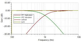
for a crossover frequency at 1 kHz (-6.1 dB) :
hi-pass: order 1 at 384 Hz, order 2 at 1.170 kHz Q=0.633, delay 180 µs, inverted.
lo-pass: order 1 at 2.604 kHz, order 2 at 855 Hz, Q=0.633.
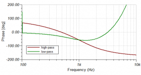
The corresponding diagrams are attached.
In my system, the resonances of the medium and the tweeter are submitted to transforms, so the real response of the combination of the filters and the drivers are those intended by the theory.
(1) see also Jmbee's chapters :
substrative + delay :
DCX2496 soustractif / delay - Le blog de jimbee
series and Baekgaard topology :
DCX2496 soustractif / delay - Le blog de jimbee
http://www.diyaudio.com/forums/mult...sover-high-efficiency-loudspeaker-system.html
Good phase response crossovers are well documented in Jmbee's blog (Jmbee is a DiyAudio member) :
filtre "quasi-optimal" : modèles et variantes - Le blog de jimbee (1)
It appears that, using analog schemes (or their equivalent in digital processors) trying to obtain transient perfection is almost always detrimental to other aspects of crossovers acoustic response.
A good idea of the acoustic response of a crossover can be summarised by knowing the axial response, the propagation delay response of the sum of the two ways and their phase difference.
This phase difference can appreciated by establishing the curve of the sum of the modules of the response of each ways (J-M Le Cleac'h called it the "coincidence response").
Using the post-proecessor of the Tina Spice simulator, this is the formula :
coincid(s) = abs(hi(s)) + abs(lo(s))
I've simulated and listened a lot, if not all, of the schemes of standard (NTM inlcuded) and quasi-optimal crossovers, some of them not documented by Jmbee.
It seems that I consistently prefered the response of third order filters, disliking lower or higher slopes (however Linkwitz-Riley 4th order slopes are a good help to determine an adequate crossover frequency).
It soon appeared to my eyes on the simulator window as well as to my ears in the listening room that the most appealing scheme comes from Herve00.fr (a member of DiyAudio too) :
for a crossover frequency at 1 kHz (-6.1 dB) :
hi-pass: order 1 at 384 Hz, order 2 at 1.170 kHz Q=0.633, delay 180 µs, inverted.
lo-pass: order 1 at 2.604 kHz, order 2 at 855 Hz, Q=0.633.
The corresponding diagrams are attached.
In my system, the resonances of the medium and the tweeter are submitted to transforms, so the real response of the combination of the filters and the drivers are those intended by the theory.
(1) see also Jmbee's chapters :
substrative + delay :
DCX2496 soustractif / delay - Le blog de jimbee
series and Baekgaard topology :
DCX2496 soustractif / delay - Le blog de jimbee
Attachments

Last edited:
Forr,
Thanks for highlighting the alternative quasi transient perfect xo topologies. Have you tried the Harsch XO? I find that it has an almost flat phase response with just a 55deg mild rise above the XO point. It makes pretty decent square waves too.
I will try the one you suggest with combination 1st and 2nd order slopes.
for a crossover frequency at 1 kHz (-6.1 dB) :
hi-pass: order 1 at 384 Hz, order 2 at 1.170 kHz Q=0.633, delay 180 µs, inverted.
lo-pass: order 1 at 2.604 kHz, order 2 at 855 Hz, Q=0.633.
A good idea of the acoustic response of a crossover can be summarised by knowing the axial response, the propagation delay response of the sum of the two ways and their phase difference.
Any axial response based theory, valid in one point only, is useless rubbish, but still this **** fascinates some guys as dark side of the moon, especially the phase part of it... Analyse this!😛
Last edited:
Any axial response based theory, valid in one point only, is useless rubbish, but still this **** fascinates some guys as dark side of the moon, especially the phase part of it... Analyse this!😛
If analyze and measurements lead to better sound performance i take any other side of the moon as good rubbish as your preferred rubbish 😀 generalize a conclusion of others specific systems is some claim when there is many other angles to moon than the dark side 😛
Last edited:
Hi Andrea, all classic cross-overs such as odd-order Butterworth and even-order Linkwith-Riley have the same filter shape for low- and highpass: Lowpass equals highpass mirrored at crossover frequency.For odd order do you intend, for example, an high-pass and a low-pass of different order or an hig-pass and a low-pass of 1st or 3d order?
Only one path, since what matters much with crossovers is lowpass behaviour relative to highpass behaviour. They must complement each other in amplitude and phase.Is flipped polarity, in this case, referred only to one of the two way or to both?
If one applies first a highpass of second and then one of first order to one and the same path, the resulting order is third.Why using this method it's obtained a combination of a 2nd order and of a 1st order?
Uli
X,
Any advantage for Harsch XO over linear phase using FIR?
Yes, don't need FIR as can be done with dumb IIR filters. 🙂
@GDO: why all the hatred for an alternative XO scheme that seems to provide sonic benefits using regular IIR filters? Have you tried the Harsch XO and listened to some live mic'd jazz trios, or piano? It sounds more like the instrument vs a recording of the instrument. With ease of setup via DSP and a few clicks of a mouse it's easy enough to try and no harm done if you don't like it.
Last edited:
If analyze and measurements lead to better sound performance i take any other side of the moon as good rubbish as your preferred rubbish 😀 generalize a conclusion of others specific systems is some claim when there is many other angles to moon than the dark side 😛
Sound quality assessment of an xover based on its effect to a square wave seems to me just stupid. What kind of fetichism is this? 🙄
These guys always use the same method: over emphasize the importance of an obscure point supposedly overlooked by others, and builld their show business on this.
Last edited:
Yes, don't need FIR as can be done with dumb IIR filters. 🙂
@GDO: why all the hatred for an alternative XO scheme that seems to provide sonic benefits using regular IIR filters? Have you tried the Harsch XO and listened to some live mic'd jazz trios, or piano? It sounds more like the instrument vs a recording of the instrument. With ease of setup via DSP and a few clicks of a mouse it's easy enough to try and no harm done if you don't like it.
Been there, played with that some time. Just too easy to get biased by some rational o pseudo rational argument, and exclame, whow this sounds wonderfull, or this sucks, or...whatever. Don't believe in sound quality assessment, just try to make things as good as i can and enjoy the result without expecting any miracle.
Last edited:
You need flat phase speaker for transient perfect.
No. You need flat group delay, which is the same as linear phase response.
It's helpful to remember this difference by thinking like this: you want all frequencies to arrive at the same time, so they should have the same amount of delay. Phase lag, in degrees or radians, is like -delay*frequency, so the phase will be linearly increasing with frequency for a fixed delay.
An externally hosted image should be here but it was not working when we last tested it.
See: https://en.wikipedia.org/wiki/Group_delay_and_phase_delay
IMHO "transient perfect" and "time aligned" are really not super important compared to other aspects of loudspeaker design. Keep in mind that the drivers themselves also have a phase response that must be included in any delay consideration. Do not just look at the response of the crossover itself.
Last edited:
- Status
- Not open for further replies.
- Home
- Loudspeakers
- Multi-Way
- A transient response simulator