Thank you indeed Sofaspud for all your invaluable expertise & advice! Yes, I too was actually thinking on the same lines,ie; using 2 rectangular LEDS glued together & then perhaps heat-shrink sleeved it as you've suggested. The more I think about this ,the more viable this appears.
Perhaps, I should go for this solution & save all you guys valuable time! Thank you all just the same for all the interesting ideas & solutions shared.
Cheers
Perhaps, I should go for this solution & save all you guys valuable time! Thank you all just the same for all the interesting ideas & solutions shared.
Cheers
Sorry...Sofaspud, I don't understand this, could you please explain how I can connect to a lightpipe? & make 4 state status connection? Could you possibly provide a schematic if you don't mind? This would be extremely useful to me!
I was planning on utilizing 2 pin LEDs....would these sufficeor do I need different type LED?
Thanks
I was planning on utilizing 2 pin LEDs....would these sufficeor do I need different type LED?
Thanks
If you can manage with a single LED, wire it from +v to -v with a suitable resistor and zener in series. The zener should drop at least half of the combined supply voltage. For example, +- 50 v supplies: Zener drops 25 volts or so, LED and resistor drops the rest.
If either supply dies, the LED goes out.
If either supply dies, the LED goes out.
If you can manage with a single LED, wire it from +v to -v with a suitable resistor and zener in series. The zener should drop at least half of the combined supply voltage. For example, +- 50 v supplies: Zener drops 25 volts or so, LED and resistor drops the rest.
If either supply dies, the LED goes out.
Thanks, this seems to be a neat idea, but I'm worried about inroducing more noise to the circuit by adding the zener diode in addition to the noise already generated by the LED! However, I will absolutely try your suggestion & report back. How much noise can one expect to inroduce by addition of the LED & the Z.diode in an audio circuit? (acoustic guitar preamp)
You have been proposed viable solutions suitable for all the LED types you showed in your previous post.Thank you indeed Sofaspud for all your invaluable expertise & advice! Yes, I too was actually thinking on the same lines,ie; using 2 rectangular LEDS glued together & then perhaps heat-shrink sleeved it as you've suggested. The more I think about this ,the more viable this appears.
Perhaps, I should go for this solution & save all you guys valuable time! Thank you all just the same for all the interesting ideas & solutions shared.
Why would you want to make things difficult for yourself by trying to make your own bi-color LED?
Sorry...Sofaspud, I don't understand this, could you please explain how I can connect to a lightpipe? & make 4 state status connection? Could you possibly provide a schematic if you don't mind? This would be extremely useful to me!
I was planning on utilizing 2 pin LEDs....would these sufficeor do I need different type LED?
Thanks
I had in mind "jelly bean" 2-pin 3mm LEDs, probably of contrasting colors to provide a good visual aid, connected to a 5mm light pipe. It amounts to a DIY bicolor LED. +V and -V combine for a third color, and nothing in case of total psu failure (or the unit is Off). The connections will be the common series resistor hookup.
Attachments
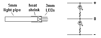
I had in mind "jelly bean" 2-pin 3mm LEDs, probably of contrasting colors to provide a good visual aid, connected to a 5mm light pipe. It amounts to a DIY bicolor LED. +V and -V combine for a third color, and nothing in case of total psu failure (or the unit is Off). The connections will be the common series resistor hookup. Today 08:37 AM
Good idea...I've just ordered a few different LEDs...it's time to experiment a little with these I think!
Good idea...I've just ordered a few different LEDs...it's time to experiment a little with these I think!
... How much noise can one expect to inroduce by addition of the LED & the Z.diode in an audio circuit? (acoustic guitar preamp)
Not a lot. It will depend, of course, on the topology (circuit design) of the preamp, which will determine how susceptible it is to noise on the power supply rails. Any noise will be injected equally (and in anti-phase with respect to ground) to both rails at once. If the preamp uses a balanced topology, the + and - rail noise will tend to cancel. It can actually be quieter than two LEDs, one for each rail, because the two LEDs will be two separate noise sources which do not cancel.
You have been proposed viable solutions suitable for all the LED types you showed in your previous post.
Why would you want to make things difficult for yourself by trying to make your own bi-color LED?
Sorry....I somehow managed to miss your earlier post! Thanks indeed. I will certainly try the 1st circuit which looks easier than the 2nd. Oh no, I've no desire what so ever in making my own LEDs...not in this life anyway!
1) The desired pinout doesn't appear to be available.Why would you want to make things difficult for yourself by trying to make your own bi-color LED?
2) This is a DIY forum.
3) A light pipe is optional; the same effect could be achieved with only a diffuser lens. Not the most difficult solution submitted.
Elvee I just tried your circuit & it works! Since I didn't have any 3 pin common cathode LED on hand I used 2 x 2 pin LEDs. However these 3 pin bicolor LEDs are freely available & I have now ordered a few.
There's no need to use RGB/ 4 pin LEDs at all as bicolor ones work just fine.
The voltages too are at + 1.12v & -1.79 respectively & very well balanced brightness between the red & the blue LEDs!
Thanks again & I'm really sorry that I unintentionally missed your 1st post.
There's no need to use RGB/ 4 pin LEDs at all as bicolor ones work just fine.
The voltages too are at + 1.12v & -1.79 respectively & very well balanced brightness between the red & the blue LEDs!
Thanks again & I'm really sorry that I unintentionally missed your 1st post.
While waiting for my bi-color diodes to arrive, I was doing a bit of reading & understood the following;
The wiring for the bi-color LED is considered “inverse parallel”; that is, one is forward and one is backward. This means that only one of the dies can be lit at a time. Current flow alternates between dies in order to produce color variation. (blinking effect)
So, does this mean that I need to use a Tri-color LED for Elvee's circuit?
If you refer to the schematic on the right in this post: http://www.diyaudio.com/forums/power-supplies/224274-single-led-dual-dc-supply-2.html#post3257053 , the red and green LEDs are not simultaneously lit (that would be an impossibility), but their supply is chopped at the line frequency, positive red negative green, and to the eye the resulting effect will be a steady yellow, not blinking red and green.While waiting for my bi-color diodes to arrive, I was doing a bit of reading & understood the following;
The wiring for the bi-color LED is considered “inverse parallel”; that is, one is forward and one is backward. This means that only one of the dies can be lit at a time. Current flow alternates between dies in order to produce color variation. (blinking effect)
So, does this mean that I need to use a Tri-color LED for Elvee's circuit?
Yeah, more or less, but there are also other types of RGBWell, it appears that bicolor 3 pin LEDs are also sometimes referred to as tricolor, just as the 4 pin tricolor ones which are also known by the acronym RGB led, Right?
If you refer to the schematic on the right in this post: http://www.diyaudio.com/forums/power-supplies/224274-single-led-dual-dc-supply-2.html#post3257053 , the red and green LEDs are not simultaneously lit (that would be an impossibility), but their supply is chopped at the line frequency, positive red negative green, and to the eye the resulting effect will be a steady yellow, not blinking red and green.
Yeah, more or less, but there are also other types of RGB
Thanks again Elvee, your 1st circuit on the left actually works very nicely.So I'd stick to that. What really surprised me, was the numerous variations in LED types available in every sphere of consumer, transport, medical & electronics!
I am now trying to find a very low current bipolar led either in 3 or 5 mm. So far I've manged to find these only in 20mA/LED = 40mA versions.
Question
If I used a 20mA very high luminous intensity LED with a resister close to Vf cut off point, would it have the same effect as a low current led or does the dropped current across the R just ends up wasted as excessive heat?
Question
If I used a 20mA very high luminous intensity LED with a resister close to Vf cut off point, would it have the same effect as a low current led or does the dropped current across the R just ends up wasted as excessive heat?
What you mean exactly is not very clear for me (and perhaps for you too).
Basically, the emitted luminous intensity is directly proportional to the forward current; the exact Vf is not known with accuracy, it depends on the color, the batch and the temperature.
What you do is to choose a sufficient large supply voltage to make variations small, and keep the current more or less constant. The LED itself has to decide what its voltage will be, you mustn't try to impose it.
The ballasted voltage in the resistor will always end up in heat.
Note that a low current LED and a high intensity one are basically the same thing: they emit a large luminous intensity at some (arbitrarily chosen) low current
Ok,I admit I wasn't very clear in my previous post, but you have actually answered part of my question!
So let me phrase it differntly. Let's assume that I want to use a LED with a lum.intensity of 400 & a forward current,iF=35mA. Now if I reduce the the current by increasing value of the R in series with the LED (& the intensity) then, would it be same as using a low current LED or is it just this reduction in current is just generated/wasted as heat across the R & still be drawing 35mA total across the resistor. I hope I made myself clearer this time!
Apparently, there are no low current bipolar leds available & most have iF of between 20mA-35mA/led! So I need to decide whether I need to use 2 x 2 pin low current leds instead!
A reduction in current cannot be generated or wasted. That'd be equivalent to the ol' "How much dirt can be shoveled out of a hole..."
The function here is an indicator LED. So it needs to be easily seen. That's all. LEDs have a specified If rating at a specified Vf. Like other diodes, the actual Vf will vary slightly with changes in If.
Also, it is technically incorrect to say anything draws 35mA across. The current flows through a resistance and creates a voltage drop across the resistor.
So to get back to your project, the series resistors will drop all the rail voltage minus the diode drops and minus the Vf of the LEDs. The Vf of the LED will be precisely set by the current through it, but the variation will be small enough to ignore. So choose a resistor value big enough to limit the current shunted through the indicator circuit. That means Elvee's values or higher. You can go as high as you want until the indicators stop indicating.
There's no reason a 20mA LED has to be run at 20mA, just like a 50V capacitor doesn't need 50V across it, a 5A transistor doesn't need 5A through it, a 12V 10A power supply doesn't need to supply 10A, a 100W amp doesn't need to output 100W, etc. They all work fine below their nominal or maximum ratings.
No, the supply voltage and dropping resistor will impose the current. You have to calculate it using Ohm's law.Now if I reduce the the current by increasing value of the R in series with the LED (& the intensity) then, would it be same as using a low current LED or is it just this reduction in current is just generated/wasted as heat across the R & still be drawing 35mA total across the resistor. I hope I made myself clearer this time!
You can decide to apply 500mA to a 50mA LED (and fry it in the process) as well as 5mA (it will shine normally).
You can also use the 50mA maximum, but you will probably need sunglasses to operate your gear; not a very good idea.
For signalling applications, intensities in the low mcd are adequate.Apparently, there are no low current bipolar leds available & most have iF of between 20mA-35mA/led! So I need to decide whether I need to use 2 x 2 pin low current leds instead!
If you find a 50mA/100mcd part, you can use it at 2mA, it will give 4mcd, more than sufficient.
- Status
- This old topic is closed. If you want to reopen this topic, contact a moderator using the "Report Post" button.
- Home
- Amplifiers
- Power Supplies
- A single LED on an dual DC supply?