

You can test it with this loudspeaker simulating circuit to see the Bode plot with a "real" load.

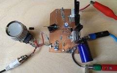
Here is last three trannies working version. No need for Q3 emitter resistor, but current must be measured, those BD139 don't like big current. Here it is around 330mA through whole amp. R7 can be adjusted or here resistor + trim.pot in series is a good choice also. Sounds good enough.

Some help, original JLH articles here :
https://sound-au.com/tcaas/index-1.htm
And PLH article by Nelson Pass :
https://www.passdiy.com/gallery/amplifiers/the-plh-amplifier
And something from this forum :
All these are big help to work with these small amps 🙂 Needs time to read all these ...
https://sound-au.com/tcaas/index-1.htm
And PLH article by Nelson Pass :
https://www.passdiy.com/gallery/amplifiers/the-plh-amplifier
And something from this forum :
What to do when you have two large heat sinks (0.3 K/W) and a large toroid (2x18 V, 500 VA)? The answer came to me when reading Mr. Pass' article about the PLH amplifier, see http://www.passdiy.com/pdf/PLH_amplifier.pdf. Mr. Pass started with the JLH amplifier from 1969, the schematic of this amplifier is shown, at http://www.tcaas.btinternet.co.uk/jlh1969.pdf, and made his own MOSFET two stage amplifier (omitting the input transistor). So I decided to try an all-FET three stage amplifier.
All these are big help to work with these small amps 🙂 Needs time to read all these ...
Some measurements using 8ohm resistor as load.
First 50kHz square (timediv 5uS, voltsdiv 0.5V)

And 1kHz sine @2.5Vrms (voltsdiv 1V)

This can give say only half-watt with smaller distortion (not measured) and around 0.8W with big distortion one-Watt shows big distortion, but with low power this works well, some more current is really good idea.
First 50kHz square (timediv 5uS, voltsdiv 0.5V)
And 1kHz sine @2.5Vrms (voltsdiv 1V)
This can give say only half-watt with smaller distortion (not measured) and around 0.8W with big distortion one-Watt shows big distortion, but with low power this works well, some more current is really good idea.
Yes, added bias to around 400mA but for sure 500mA is better and needs even bigger heatsinks 😃View attachment 1440889
worse performance than my amplifier but 300ma less of bias current, mine was biased to 700ma while this one only uses up 400/300ma.
View attachment 1440892
its performance is better at 500ma bias current.
If you want something with 2 output transistors, 2 drivers, biased at ~ 300mA, no feedback, no gain, almost no distortion, few watts, check out 'adason' buffer. Well, i did not name it that, others did. I build many versions with various outputs, they all worked great.
Post in thread 'Output BJTs for buffer' https://www.diyaudio.com/community/threads/output-bjts-for-buffer.386324/post-7024034
Post in thread 'Output BJTs for buffer' https://www.diyaudio.com/community/threads/output-bjts-for-buffer.386324/post-7024034
Why not , but with added distortion and output impedance. Better to use at least two trannies.We could also use just a single transistor.
why all PNP instead of all NPN?
Yes, I have some GE transistors also, not just these one, but maybe similar enough.
- Home
- Amplifiers
- Solid State
- A simple discrete one-watt amplifier