Hello
A circuit with an output stage using transistors of the same conductivity with differential amplifier as a driver has been known for quite a long time. I took it as a basis and made a very simple amplifier with good parameters.

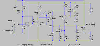
P407 sets the quiescent current, P413 sets half the power at the output. I used KT819 output transistors, but any powerful NPN transistors can be used.
To thermally stabilize the quiescent current, D34D35 diodes are installed on a radiator with output transistors.
The 3dB bandwidth is 100kHz. By increasing the capacitance of C138, you can reduce the bandwidth, but this leads to an increase in distortion.
THD does not exceed 0.015% over the entire output voltage range. The output spectrum is dominated by the second and third harmonics. Their levels are approximately the same.
The circuit was assembled on a breadboard. Now I'm making printed circuit boards for this amplifier.
A circuit with an output stage using transistors of the same conductivity with differential amplifier as a driver has been known for quite a long time. I took it as a basis and made a very simple amplifier with good parameters.
P407 sets the quiescent current, P413 sets half the power at the output. I used KT819 output transistors, but any powerful NPN transistors can be used.
To thermally stabilize the quiescent current, D34D35 diodes are installed on a radiator with output transistors.
The 3dB bandwidth is 100kHz. By increasing the capacitance of C138, you can reduce the bandwidth, but this leads to an increase in distortion.
THD does not exceed 0.015% over the entire output voltage range. The output spectrum is dominated by the second and third harmonics. Their levels are approximately the same.
The circuit was assembled on a breadboard. Now I'm making printed circuit boards for this amplifier.

Same sex, yes - but not a QC topology. Q93 and 94 are same sex also. It’s a variation on a circlo. I’m sure it does sound good (better than a equally simple QC, which will tend to have a lot of crossover distortion).
Yes, you are right - the topic name is not correct, but I can’t change it anymore.
Perhaps moderator can change it to something like “A simple amplifier with an output stage using transistors of the same conductivity”
Perhaps moderator can change it to something like “A simple amplifier with an output stage using transistors of the same conductivity”
If you turn the circuit upside down, then the output stage can be implemented using a Sziklai pair. The following diagram was assembled

As expected, the maximum output voltage increased from 7.8V to 8.4V rms. But distortions have increased
As expected, the maximum output voltage increased from 7.8V to 8.4V rms. But distortions have increased
Very nice UR5FFR! very good low distortion for a simple design. I'd like to see how well darlington's would work as output transistors or even FET's?
How is stability from oscillation?
How is stability from oscillation?
LV's Circlo uses the same idea but he has included idle current sensing to make it more thermal stable.
https://www.diyaudio.com/community/threads/my-little-cheap-circlophone-c.189599/
Others and I have played with NPN only topologies with modest success. It's fun to find solutions to old problems and perhaps an NPN only circuit could still be useful in monolithic chips. But realistically today there is little point except novelty. I can get diode-based outputs (~TTL logic) down to about 0.01%THD in simulation and current mirror designs a bit better. Many people still love the JLH style circuits, mostly class-A amps which are similar, but the THD numbers are not great, especially for class-A. A little even harmonic profile may be a good thing. If you will allow any PNP then it's hard to beat a well-done Quasi, especially if you use auto-bias that senses the base current. LV etc. also posted outputs where one output is non-switching, and the other is driven as required to keep the first conducting.
Attachments
Thank you!Very nice UR5FFR! very good low distortion for a simple design. I'd like to see how well darlington's would work as output transistors or even FET's?
How is stability from oscillation?
The first scheme with Darlingtons works quite stably - I did not detect any self-excitation. I haven't tried installing mosfets. In my opinion, this will lead to a decrease in the maximum output voltage by about 1V because Mosfets require higher gate-to-source voltage than bipolar transistors.
The second scheme with the Szyklai pair works less stable in my opinion. I tried to reduce distortion by reducing the load on the differential stage using additional Q216 and Q217. This has somewhat reduced the distortion, but this circuit still loses to the Darlington circuit.
Please note that my amplifier operates in class AB, not class A!
It is easy to implement strict stabilization of the quiescent current in the amplifier, which allows it to operate in class A.
Resistor R446 is a current sensor. As the quiescent current increases, the voltage at the emitters of the Q219/Q222 transistors decreases, and the current through them decreases. This results in a decrease in current through the output transistors.
The use of C159 leads to the fact that when turned on, the current through the output transistors increases smoothly to the maximum value.
I haven't tested this in detail, but it works. Its output spectrum is short - the second harmonic predominates. The third is also there but with a smaller amplitude. There are no harmonics higher than the third in the spectrum - they are at the noise level or lower.
This circuit should not be taken as final and complete, but perhaps this circuit will serve as a good starting point for someone to experiment with class A amplifiers.
Thank you! Is it push-pull in class A? Is it possible to convert the circuit with pnp output transistors?
I can hardly help you with anything - due to Russian missile attacks on my country and my city, I only have electricity 10 hours a day, and sometimes less. Therefore, I can devote very little time to hobbies
Some will remember this one:
https://www.diyaudio.com/community/...nly-1-type-of-transistors.354589/post-6207406
https://www.diyaudio.com/community/...nly-1-type-of-transistors.354589/post-6207406
- Home
- Amplifiers
- Solid State
- A simple amplifier with an output stage using transistors of the same conductivity