I also have to set up some global variables. Because I'm controlling hardware, it's useful to keep track of the global state of various things, and let each function fiddle with state as needed. I know it's not the greatest programming practice - very little information hiding - but it's going to have to do for now.
Actually it is a good practice you do.
I do not work with Arduino, but with AVR tiny and mega MCUs programming in C (which is doable in Arduino IDE as well) so I will not review your Arduino code but if you are stuck somewhere, feel free to send me a message explaining the problem, I will help when I can.
Working on the power supply
Here are a couple of pictures of the power supply. I decided to put the transformers, all the mains circuitry, and the regulators in a separate metal box, well away from the sensitive analog circuitry. This is an approach that has served me well in the past.
I found a long thin aluminum box that will sit nicely on the floor near the preamp, and close to the power source.
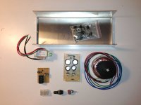
The 5V power supply uses a regular, non-toroidal transformer, which is more prone to broadcasting a magnetic field, so it's down the "nasty" end with the mains circuitry. Once I get everything working, I'll look at the quality of the power coming off the rails on the oscilloscope to check that all is well.
I haven't figured out the best approach to grounding yet - I may have analog and digital ground wires running to the preamp, joined at the ground point in the power supply. I want to keep the digital circuitry, motor controller and relay power away from the analog audio world as far as possible.
Here's the current state of play: the 5V is wired up and working; the toroid is producing 2 x 15VAC, and I'm getting ready to install and test the analog regulators.
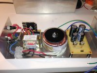
The other thing that's still outstanding is what kind of wire to use to take the power to the preamp. I'm thinking of using two separate shielded cables. Probably overkill...
I tend not to use plugs if I can avoid them for things like this - I expect to move the system hardly ever, so I don't mind if the two boxes are permanently connected.
Looking at the second photo, I can see a lot of metal filings on the case - I'll give it a good clean before I am finished😱. I had to file the power cable hole because it was too tight a fit, and my stepped bit only goes up to 1/2"...
Here are a couple of pictures of the power supply. I decided to put the transformers, all the mains circuitry, and the regulators in a separate metal box, well away from the sensitive analog circuitry. This is an approach that has served me well in the past.
I found a long thin aluminum box that will sit nicely on the floor near the preamp, and close to the power source.

The 5V power supply uses a regular, non-toroidal transformer, which is more prone to broadcasting a magnetic field, so it's down the "nasty" end with the mains circuitry. Once I get everything working, I'll look at the quality of the power coming off the rails on the oscilloscope to check that all is well.
I haven't figured out the best approach to grounding yet - I may have analog and digital ground wires running to the preamp, joined at the ground point in the power supply. I want to keep the digital circuitry, motor controller and relay power away from the analog audio world as far as possible.
Here's the current state of play: the 5V is wired up and working; the toroid is producing 2 x 15VAC, and I'm getting ready to install and test the analog regulators.

The other thing that's still outstanding is what kind of wire to use to take the power to the preamp. I'm thinking of using two separate shielded cables. Probably overkill...
I tend not to use plugs if I can avoid them for things like this - I expect to move the system hardly ever, so I don't mind if the two boxes are permanently connected.
Looking at the second photo, I can see a lot of metal filings on the case - I'll give it a good clean before I am finished😱. I had to file the power cable hole because it was too tight a fit, and my stepped bit only goes up to 1/2"...
Actually it is a good practice you do.
I do not work with Arduino, but with AVR tiny and mega MCUs programming in C (which is doable in Arduino IDE as well) so I will not review your Arduino code but if you are stuck somewhere, feel free to send me a message explaining the problem, I will help when I can.
I think it will work. I'm basically a fan of side-effect-free programming, in which you should be able to understand the behavior of code without having to understand potential data changes from afar, but hardware is not like that obviously - it changes in its own time. So long as it's well documented, it should be OK.
I'm trying to keep the code for each object type (rotary encoder, volume control, IR etc.) in it's own file, and to write simple functions. It may be less efficient for the microcontroller, but it's more efficient for me.
And thanks for the offer of help...I'll let you know if (when?) I get into trouble.
tim
Last edited:
Progress with the power supply
I now have all three power rails working. The 5V was easy, but I had no end of trouble with the 15V supply. One mistake was that I'd inverted the pins on the -ve regulator, leading to a burned out resistor in the CRC pre-filter.
In replacing the regulator (part of discovering what was wrong), I tore up a bit of the copper, so I had to do a lot of multimeter tracing. Eventually that was all fixed.
The last problem was that I couldn't get the right voltages out of both + and - at the same time. I eventually wondered if the 10 ohm resistors in my CRC were causing the problem, as I was testing the power supply with no load. It seemed plausible that there was too much voltage drop over them, and the regulator wasn't getting enough. Right or wrong, I bypassed the resistors, and now I have a good 15V on each side.
I found a shielded cable with 8 conductors and a shield at Markertek - they also stock a variety of other things I was looking for - RCA plugs and sockets, and an XLR plug and socket for the power at the preamp end. I've decided to have a fixed cable coming out of the power supply, with a plug and socket at the preamp end. It will just make installation that much easier. As XLR plugs lock, I am expecting a reliable and long-lived connection.
Here's the "finished" preamp power supply. I still have to do the output wiring.
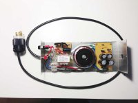
The mains plug is a Marinco. I bought a stack of them a few years ago and they seem to work well. The 10 ohm CRC resistors are on the bottom of the regulator board at the right hand side of the photo.
I now have all three power rails working. The 5V was easy, but I had no end of trouble with the 15V supply. One mistake was that I'd inverted the pins on the -ve regulator, leading to a burned out resistor in the CRC pre-filter.
In replacing the regulator (part of discovering what was wrong), I tore up a bit of the copper, so I had to do a lot of multimeter tracing. Eventually that was all fixed.
The last problem was that I couldn't get the right voltages out of both + and - at the same time. I eventually wondered if the 10 ohm resistors in my CRC were causing the problem, as I was testing the power supply with no load. It seemed plausible that there was too much voltage drop over them, and the regulator wasn't getting enough. Right or wrong, I bypassed the resistors, and now I have a good 15V on each side.
I found a shielded cable with 8 conductors and a shield at Markertek - they also stock a variety of other things I was looking for - RCA plugs and sockets, and an XLR plug and socket for the power at the preamp end. I've decided to have a fixed cable coming out of the power supply, with a plug and socket at the preamp end. It will just make installation that much easier. As XLR plugs lock, I am expecting a reliable and long-lived connection.
Here's the "finished" preamp power supply. I still have to do the output wiring.

The mains plug is a Marinco. I bought a stack of them a few years ago and they seem to work well. The 10 ohm CRC resistors are on the bottom of the regulator board at the right hand side of the photo.
Utility functions: Display
I like to keep code in simple blocks. It's easier to understand and I find a certain pleasure in clarity.
Here's the code to drive the display. In writing Arduino code, it's possible to put the code into multiple files, which appear as separate tabs in the IDE. They are all concatenated before compilation if you just name them "display" or something like that, so you don't have to worry about header files etc.
Another benefit is that I can copy this code easily into another sketch for purposes of testing, which will be important as the system starts to come together.
First a couple of support functions:
When command mode is active, I put a border of "#" symbols on the left and right.
Then there are functions to display volume, input (source), and the current mode settings:
And finally, functions for splash screen, standby, and initialization.
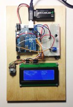
I made a quick lashup to test the display - I can now test the display and IR, and part of the volume code (the little blue pot provides sense input as if the volume control was attached).
I like to keep code in simple blocks. It's easier to understand and I find a certain pleasure in clarity.
Here's the code to drive the display. In writing Arduino code, it's possible to put the code into multiple files, which appear as separate tabs in the IDE. They are all concatenated before compilation if you just name them "display" or something like that, so you don't have to worry about header files etc.
Another benefit is that I can copy this code easily into another sketch for purposes of testing, which will be important as the system starts to come together.
First a couple of support functions:
Code:
void status(char * message)                     // utility function for debugging
///////////////////////////
{
  Lcd.setCursor(0, 3);
  Lcd.print("                    ");
  Lcd.print(message);

}

void printError(char* error)                    // Print an error message on the display
////////////////////////////
{
  Lcd.setCursor(0,0);
  Lcd.print(error);
}
Code:
void displayCommandActive(boolean active)      // print # along left and right if we're in command mode
/////////////////////////////////////////
{
  static char c;

  c = active ? '#' : ' ';
  Lcd.setCursor(0, 0);
  Lcd.print(c);
  Lcd.setCursor(19, 0);
  Lcd.print(c);
  Lcd.setCursor(0, 1);
  Lcd.print(c);
  Lcd.setCursor(19, 1);
  Lcd.print(c);
}
Code:
void displayVolume(byte vol)
////////////////////////////
{
  Lcd.setCursor(6, 0);
  Lcd.print("    ");                           // padding spaces to wipe out the previous volume
  Lcd.setCursor(6, 0);                         // go back again...
  Lcd.print(vol);
}

void displayInput(byte in)
////////////////////////////
{
  static const char* inputs[] = {
    "Phono", "CD   ", "DAC  ", "Tuner", "Tape "    };  // padding spaces to make sure we overwrite whatever was there before
  Lcd.setCursor(1, 0);
  Lcd.print(inputs[in]);
}

void displayMonitor(boolean mon)
////////////////////////////
{
  Lcd.setCursor(1, 1);
  if (mon)
    Lcd.print("Monitor");
  else
    Lcd.print("Source ");
}

void displayDSP(boolean val)
////////////////////////////
{
  Lcd.setCursor(12, 1);
  if (val)
    Lcd.print("DSP");
  else
    Lcd.print("   ");
}

void displayMute(boolean val)
////////////////////////////
{
  Lcd.setCursor(12, 0);
  if (val)
    Lcd.print("MUTE");
  else
    Lcd.print("Play");
}
Code:
void displaySplash(int ms)
//////////////////////////        Show splash screen, then pause for ms milliseconds
{
  Lcd.begin(16, 2);                       // LCD size may change in final
  Lcd.setCursor(2, 0);
  Lcd.print("Arduino and ESP");
  Lcd.setCursor (5, 1);
  Lcd.print("RC Preamp");
  delay(ms);
}

void displaySignoff()
/////////////////////
{
  Lcd.clear();
  Lcd.setCursor(0, 1);
  Lcd.print("Powering down");
  delay(2000);
}

void displayInit()
//////////////////
{
  Lcd.clear();
  displayVolume(volumeGet());
  displayInput(Input);
  displayMonitor(Monitor);
  displayDSP(Dsp);
  displayMute(Mute);
}
I made a quick lashup to test the display - I can now test the display and IR, and part of the volume code (the little blue pot provides sense input as if the volume control was attached).

Progress on the enclosure
I have used 1-1/2" x 1-1/2" x 1/8" aluminum angle for a few projects with plywood base and top. It's fairly easy to work and doesn't look terrible. I like my projects to look home-made (not sloppy, just handcrafted).
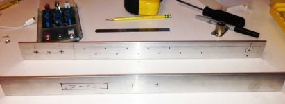
Here's the first step: marking out the front and back of the case:
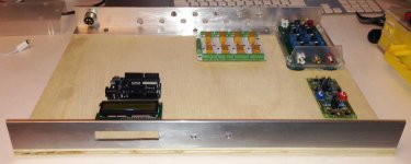
And now after drilling, lots of space for all the bits.
I just sanded the front and back panels. I may clear-coat them later.
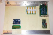
Since these pics I've installed the RCA sockets and the 4-pin XLR for power; also I have worked out a mounting scheme for the display - basically a block of plywood to hold it in place. More pics to come.
The downside of plywood as an enclosure material is warping - the base doesn't sit quite flat, so it's being clamped for a few days. We'll see if it straightens out...
I have used 1-1/2" x 1-1/2" x 1/8" aluminum angle for a few projects with plywood base and top. It's fairly easy to work and doesn't look terrible. I like my projects to look home-made (not sloppy, just handcrafted).
Here's the first step: marking out the front and back of the case:

And now after drilling, lots of space for all the bits.

I just sanded the front and back panels. I may clear-coat them later.

Since these pics I've installed the RCA sockets and the 4-pin XLR for power; also I have worked out a mounting scheme for the display - basically a block of plywood to hold it in place. More pics to come.
The downside of plywood as an enclosure material is warping - the base doesn't sit quite flat, so it's being clamped for a few days. We'll see if it straightens out...
Code, code, and some hardware hacking
I spent the day reworking the code: I now have the rotary encoder and infrared remote working.
The changes had mostly to do with the sequencing within the user interface and cleaning up the display. I'm not sure anyone wants to read all my code, but I might post some bits as things develop.
I am also now going to try a PGA 2310 as a volume control. I haven't used one before, but I think it should be doable. I'll probably have to make a few mods to the preamp analog stage to manage the overall gain, but we'll see. As the preamp is in two stages with (normally) a pot in between, I think I can just insert the PGA after the first stage. Fortunately the gain of Rod Elliott's preamp is settable with DIP switches, so I should be able to find a setting that works.
I'm planning to use a prototyping board for the PGA, which I realize may be a bit risky from a noise perspective (no ground plane), but we'll see. I can at least keep digital and analog separate.
Putting it all together
Well, that's not really going to happen for a while. But I am beginning to get things working in the box, which is satisfying.
I have revised the user interface, and it's now running with the remote control and the rotary encoder.
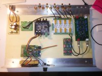
Here's an overview of the box - all the bits are there except for the PGA volume control board, which I haven't built yet. I'm starting to do the signal wiring.
I haven't quite decided yet on the order of the different modules. I want to be able to use the MiniDsp as if it was in a tape loop, and I'm thinking of installing it before the volume control, and after the first stage of preamplification. The only difficulty with that is that I can't really use all four outputs, and I am thinking of adding a subwoofer eventually.
So I may be better to make the MiniDSP the final stage, with its four outputs going to separate phono plugs. Then I can have a couple of modes - one where the output of the preamp goes directly to two output sockets, and the other where the same pair of sockets get the output of the DSP. The MiniDSP would always feed a couple of output sockets with its #3 and#4 outputs.
I'm really not sure of the best way to do this. The preamp will be 20' from the power amp, so I need good line drive capability, and I don't know how good the MiniDSP will be over those distances.
So your thoughts, insights and ideas are welcome.
Well, that's not really going to happen for a while. But I am beginning to get things working in the box, which is satisfying.
I have revised the user interface, and it's now running with the remote control and the rotary encoder.
Here's an overview of the box - all the bits are there except for the PGA volume control board, which I haven't built yet. I'm starting to do the signal wiring.

I haven't quite decided yet on the order of the different modules. I want to be able to use the MiniDsp as if it was in a tape loop, and I'm thinking of installing it before the volume control, and after the first stage of preamplification. The only difficulty with that is that I can't really use all four outputs, and I am thinking of adding a subwoofer eventually.
So I may be better to make the MiniDSP the final stage, with its four outputs going to separate phono plugs. Then I can have a couple of modes - one where the output of the preamp goes directly to two output sockets, and the other where the same pair of sockets get the output of the DSP. The MiniDSP would always feed a couple of output sockets with its #3 and#4 outputs.
I'm really not sure of the best way to do this. The preamp will be 20' from the power amp, so I need good line drive capability, and I don't know how good the MiniDSP will be over those distances.
So your thoughts, insights and ideas are welcome.
I just remembered that the MiniDSP has its own volume control. If I put it between the two stages of the preamp, I can control the volume by sending a PWM output to the control pin on the DSP. This creates the simplest possible volume control - no need for a PGA or a pot.I haven't quite decided yet on the order of the different modules. I want to be able to use the MiniDsp as if it was in a tape loop, and I'm thinking of installing it before the volume control, and after the first stage of preamplification. The only difficulty with that is that I can't really use all four outputs, and I am thinking of adding a subwoofer eventually.
So I think I'll try this first (means I have to rewrite a few lines of code, but nothing spectacular).
I think that I could do the same with the miniDSP at the end of the chain, but I'll probably start with it in the middle.
Here's a link describing the approach.
A couple of GUI shots
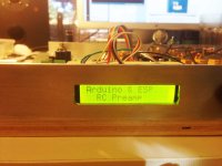
Here are a couple of shots showing the GUI - I haven't built custom characters, just using standard ASCII.
This is the splash screen:
and here's the main screen during operation.
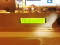
Volume is displayed in dB and as a bar graph. The input appears at the left. The "D" means the DSP is enabled.
This is the screen for the balance control. The "><" turns into "<>" when balance is off center.
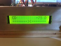
I need to do a bit more work on my hand-made cutout - the fact that it's illuminated means that flaws in my workmanship are very visible. Maybe I'll create some kind of bezel when I have time (and it's all working).
Here are a couple of shots showing the GUI - I haven't built custom characters, just using standard ASCII.
This is the splash screen:

and here's the main screen during operation.

Volume is displayed in dB and as a bar graph. The input appears at the left. The "D" means the DSP is enabled.
This is the screen for the balance control. The "><" turns into "<>" when balance is off center.

I need to do a bit more work on my hand-made cutout - the fact that it's illuminated means that flaws in my workmanship are very visible. Maybe I'll create some kind of bezel when I have time (and it's all working).
First music!
It's a bit of a mess, but I was actually able to listen to music finally, after making a lot of mistakes. Rachmaninov
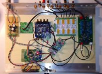
I'm hooking into the MiniDSP using it's expansion connector, and I made the cables too short, because I thought I was using the connector on the other side 🙁.
I think I tried every combination before I finally got it working. But fortunately I didn't break anything.
The relay switching is working (also took a few re-wirings), and I'm just feeding a PWM voltage to the MiniDSP as a volume control. It works fine.
I was hoping to bring it to Burning Amp, but it's too messy and fragile. I will have to go through and re-work a number of the connections to make it reliable.
Apart from the cleanup, I still have to implement the bluetooth, and there are some start-up noises I need to look at.
But the basic operation seems to be there, and there is no audible hash from the digital elements - that was my biggest fear.
It's a bit of a mess, but I was actually able to listen to music finally, after making a lot of mistakes. Rachmaninov


I'm hooking into the MiniDSP using it's expansion connector, and I made the cables too short, because I thought I was using the connector on the other side 🙁.
I think I tried every combination before I finally got it working. But fortunately I didn't break anything.
The relay switching is working (also took a few re-wirings), and I'm just feeding a PWM voltage to the MiniDSP as a volume control. It works fine.
I was hoping to bring it to Burning Amp, but it's too messy and fragile. I will have to go through and re-work a number of the connections to make it reliable.
Apart from the cleanup, I still have to implement the bluetooth, and there are some start-up noises I need to look at.
But the basic operation seems to be there, and there is no audible hash from the digital elements - that was my biggest fear.
Interesting project, thinking of doing something similar (as soon as my power amp is finished 😀).
Some remarks on your Arduino Code:
Holgi
Some remarks on your Arduino Code:
- Did you consider to use the interrupt features of your µC? The Arduino provides 2 HW interrupts and additional SW interrupts on the digital I/O's. I intend to use a HW interrupt for the IR receiver and SW interrupts for the source select encoder. This offloads these tasks to separate routines and you don't need to take care in your loop() scheduling.
- The limited I/O lines of the Arduino (I intend to use a Nano) can be dealt with best using I/O-expanders which are connected to I2C. This makes cabling pretty easy, programming is done via the Wire-Library and you can use (almost) as many I/O's as you like. My current preference is NXP's PCF8574 providing 8 digital I/O's each. Is there any reason why you're stingy with your I/O's or why you want to use a SR instead?
Holgi
The code for the rotary encoder does use interrupts. I have previously used an interrupt library to simplify control flow. However in this case I'm not really concerned about power consumption - in fact I'd rather have the microcontroller consume more or less constant power to avoid spikes that could find their way into the analog circuitry.Interesting project, thinking of doing something similar (as soon as my power amp is finished 😀).
Some remarks on your Arduino Code:
- Did you consider to use the interrupt features of your µC? The Arduino provides 2 HW interrupts and additional SW interrupts on the digital I/O's. I intend to use a HW interrupt for the IR receiver and SW interrupts for the source select encoder. This offloads these tasks to separate routines and you don't need to take care in your loop() scheduling.
Also, I'm not sure what interactions there might be between the rotary encoder interrupt code and any code that I might write. So it seemed easier to have the operating assumption that each function can block while it's processing a single command. There are things I could do to improve the smoothness of the UI - right now I use delay() to do de-bouncing and to slow down the software especially for the rotary encoder. It would be better to queue inputs or something like that so I can make more intelligent decisions about what the user is doing.
BR,
- The limited I/O lines of the Arduino (I intend to use a Nano) can be dealt with best using I/O-expanders which are connected to I2C. This makes cabling pretty easy, programming is done via the Wire-Library and you can use (almost) as many I/O's as you like. My current preference is NXP's PCF8574 providing 8 digital I/O's each. Is there any reason why you're stingy with your I/O's or why you want to use a SR instead?
Holgi
I had a 595 shift register in my parts box, so I used it. I was able to get everything done with the pins I have, so it seemed an OK solution. Also, I've never written any I2C code, and didn't have the part. At some point it seemed like a good idea to avoid adding more complexity.
But for future projects, I agree that serial communications protocols like I2C or SPI allow for much greater scalability. I also like the clean code that is possible with interrupts.
Thanks for writing.
Are you needing to debounce the encoder? After I started using a higher quality encoder, there was no need to debounce and it feels much nicer to use.
Are you needing to debounce the encoder? After I started using a higher quality encoder, there was no need to debounce and it feels much nicer to use.
I used the circuit recommended by Bourns - a couple of caps and pull-up resistors. Then I just let the encoder library do its thing. I didn't try it without the caps and resistors, so I don't know if it would work or not.
I think the Bourns is of reasonably high quality???
tim
I think the Bourns is of reasonably high quality???
Yes definitely, I have two. One is 128ppr and the other 64ppr, they are both really good. I'm not using a library (or any debounce hardware/software), I didn't realise there was one! I'll take a look. Thanks.
The source code
Here's the source code for the entire project so far. This does not include the bluetooth code because I haven't written it yet, and I don't have a way to control it from my phone anyway.
View attachment RC Preamp MiniDSP code.pdf
The balance control is also non-functional, because the MiniDSP just offers a volume control on a single pin. Input selection and volume are both controllable from either the front-panel rotary encoder or via the Apple remote.
I've been listening to music for a couple of days now - I'm still deciding what I think of it. There are a few glitches that I don't understand - changing input causes hum for a few seconds, for reasons I don't understand. It goes away quite quickly, however. There are also some initialization issues, because I don't reset the shift register and it starts up in a random configuration. As I turn on the preamp before the power amp, this is not a problem in practice.
There is no hum or noise at all when music is playing, which is a surprise and relief, given all the digital hardware.
I am not sure about the use of the MiniDSP as a volume control for the long term - I would rather have an analog volume control and run the DSP at full volume (and therefore resolution). I may yet build the PGA volume control which would give me balance as well.
There are other things I'd like to do - add acceleration to the volume control, maybe change the way the remote works (I sometimes switch inputs when I mean to change the volume). If I add a PGA volume control I can implement the relay that switches the DSP in and out of circuit, hopefully to make A/B comparisons easier.
Not bad, I've written some code for an Android phone which is bluetooth enabled.
It controls the sources, and a stepped attenuator.
It controls the sources, and a stepped attenuator.
- Status
- Not open for further replies.
- Home
- Source & Line
- Analog Line Level
- A remote control preamp in the works