
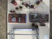
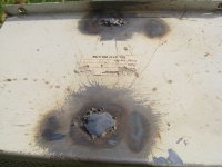
A complete strip down was required.
Attachments
Last edited:
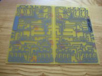
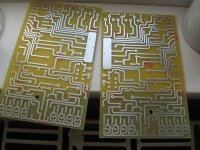
The old PCBs were pretty shot with broken traces so I put considerable effort into making a prototype new design (using the original Radford circuit), with a few tweaks (CCS cathode biasing which turned out to be a more trouble than it was worth) and a better physical layout.
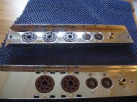
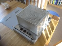
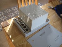
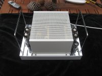
Meanwhile the metalwork I sent off to be chromed came back.
Meanwhile the metalwork I sent off to be chromed came back.
Attachments
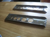

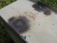
Whoops this is backwards, but before I got the painting done I had to see to those pesky holes. The welding and grinding were not done by me 🙂
Also I feel silly for posting the previous pictures already because it gives the game away so quickly 😀
Also I feel silly for posting the previous pictures already because it gives the game away so quickly 😀
Attachments
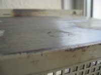
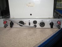
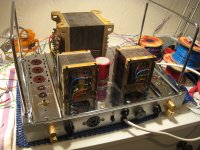
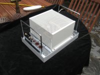
Looks great with all the metalwork chromed, The pressings holding the valves are only zinc plated standard, and they easily stain with any moisture that gets on them.
My STA 15 had MK4 upgrade PCBs fitted and then stayed in my audio system for a pleasurable 20 years of use before exploding an electrolytic. It now sits on the shelf waiting to be repaired.😱
The Mk 4 PCBs are very similar to the Mk3 but had added bi-pass polypropylene caps on most of the electrolytics. Other mods that were recommended were hard wiring the output transformer impedance tap without the selector switch. They also supplied a new input socket, and heavy duty binding posts.
I have to go and do something outside but I will be back soon with more pictures!
It looks really excellent, looking forward to seeing more pictures soon.
Will also be be quite interesting to read your impressions of the amplifier's performance once completed and put back into service.
That's real dedication to bring something back from the brink like this. I think many would have scrapped it for the transformers.
The amplifier has been long finished so I can tell you my impressions now! 😀
Me and a friend compared against his stock STA15. The restored one had a slightly cleaner sound and for some reason was actually far less fussy about the output valves used, possibly due to the CCS bias arrangement.
My friend had previously used JJ E34Ls in his STA15 which he found a bit bright to his taste, so he upgraded to some Svetlanas and is very happy with them. We listened to the restored amp with JJs (while his had the Svetlanas), and he found that the brightness of the JJs was not so apparent. These tests were done on his system so he was familiar with the music and speakers.
Another thing that seems to be different is the noise floor. With my PCB design the amp runs VERY quiet. This may be due to the metal films throughout, and the different layout of the boards....
Time for more pictures!
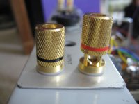
Here are some pictures of the assembly process. I tried to keep the amp as original as possible but I had to fit new binding posts, because the originals wouldn't fit in their holes due to the thickness of the new paintwork. IMO the new ones are far better anyway so this is no great loss.
Here are some pictures of the assembly process. I tried to keep the amp as original as possible but I had to fit new binding posts, because the originals wouldn't fit in their holes due to the thickness of the new paintwork. IMO the new ones are far better anyway so this is no great loss.
Attachments

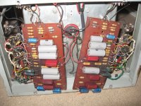
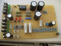
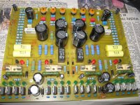
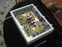
I then populated the final PCB version.
Features include cathode CCS bias, and a robust protection circuit to protect the amplifiers from runaway output valves. It works surprisingly well, in fact it has survived a shorted valve.
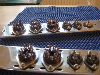
I then installed them in the amp ready for wiring.
Features include cathode CCS bias, and a robust protection circuit to protect the amplifiers from runaway output valves. It works surprisingly well, in fact it has survived a shorted valve.
I then installed them in the amp ready for wiring.
Attachments

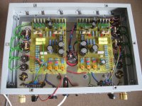
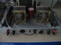
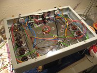
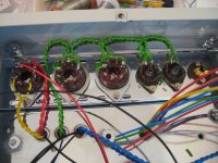
And the journey ends with me wiring up the boards!
I had a few teething problems but I eventually solved them. One was a very low frequency oscillation caused by the CSS bias, which I solved with the kind help of DF96, a frequent poster here.
Another was an extreme tendency to pick up earth loops, which I managed to fix by earthing the signal boards via low value resistors, to break the loops.
The whole project was a LOT of work!
Attachments
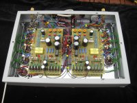
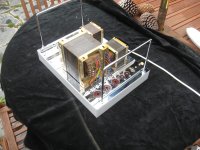
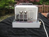
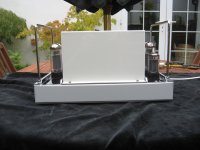
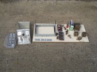
The last couple of pics.
I hope you enjoyed them! I have others but they're mostly of more specific parts of the build, this is just an overview. If anyone is curious about any specific part of the rebuild I will post relevant pictures. The owner is very happy indeed with my work. Thanks for looking 🙂
I hope you enjoyed them! I have others but they're mostly of more specific parts of the build, this is just an overview. If anyone is curious about any specific part of the rebuild I will post relevant pictures. The owner is very happy indeed with my work. Thanks for looking 🙂
Attachments

Pretty, pretty, pretty good. I'd have improved the original design though. Those handles got to go. 😀
Pretty, pretty, pretty good. I'd have improved the original design though.
I did toy with the idea but it wasn't my amplifier, and it turns out that while the amp could be improved with some modern tricks and techniques, the design really is more than the sum of its parts and makes good use of the valves. It is still a Radford STA15.
- Status
- Not open for further replies.
- Home
- Amplifiers
- Tubes / Valves
- A Radford STA15 restoration story