I was wondering if anybody has removed the SOA components from an A60?
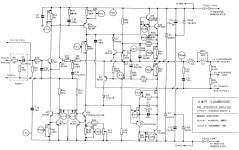
I'm not an electronics genius by a long stretch, but looking at the circuit diagram (below), it looks to me to be from the same family as the Naim power amp. I've seen quite a few threads on various boards where people report a worthwhile improvement when the SAO is removed from the Naim boards.
Comparing with those threads, I think that the SOA components on the A60 are these:
D1/Q16/A17/D2
R60/R57/R54/R53
R59/R58/C28/C29/R56/R55
So before I accidentally send an amplifier to heaven, is it a) worth it, b) safe and c) have I got the right components in my sights?
Thanks,
Duncan
Attachments
The A&R A60 (A&R are now Arcam) and the Naim amp are not related, other than that they use a similar topology.
Your list of components is correct. However, I would say there is little if anything to be gained by removing the SOA protection from the amp. If you're looking to improve sound quality, and you haven't already done it, you should replace all of the electrolytic capacitors, especially the power supply capacitors.
Your list of components is correct. However, I would say there is little if anything to be gained by removing the SOA protection from the amp. If you're looking to improve sound quality, and you haven't already done it, you should replace all of the electrolytic capacitors, especially the power supply capacitors.
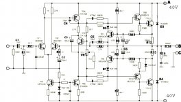
Nice to see the 4 diodes across the rails. D4, 5, 208 & 209 provide simple & very cheap protection.
Lot's of examples of adoption of very standard features/topology. Ordinary here, equals well liked by the thousands of purchasers. I see 6 stability capacitors. This could indicate a well sorted amplifier.
Now to IV protection.
A good IV protection topology should allow all valid audio signals to pass to all valid speaker loads. If A&R have done their sums right and listened to the prototypes then I would expect that the adopted component values will allow all the audio to pass without interference.
Last edited:
My college lecturer called the 2N3055 (TIP3055) the indestructable transistor. My early experimenting soon blew that theory out of the water.
As to your question, all you have to do to disable the protection is remove D1 and D2.
Whether that is wise is another matter. I suspect you will be nowhere near triggering this in normal use.
The driver transistors and VAS transistor are the weak points on this amp. These transistors can fail by going intermitent open circuit, not through overload as such, just a problem with the specific devices used.
That's my first task. Removal of the SOA was just a thought given others report improvements when done to the Naim amp, which as noted, shares the topology. I'll likely leave it as I like my amps to be close to the designer's originals.If you're looking to improve sound quality, and you haven't already done it, you should replace all of the electrolytic capacitors, especially the power supply capacitors.
Can you clarify please? I'm trying to learn as I go here. On the Naim amp there is a capacitor across the base/collector of Q13 which I've read is to stop oscillation. AKA, I think, a "Miller" capacitor? So are you talking about the non-polar caps?I see 6 stability capacitors. This could indicate a well sorted amplifier.
Is IV the same as SOA? What does it stand for?Now to IV protection.
Thanks.
Duncan
I agree with Mooly, rather improve on the vas transistor and or drivers. For vas try something like 2sa1209 or any high voltage video transistor. This can also then be used as the driver transistor.
SOA = Safe Operating Area.
IV = Current Voltage.
When applied to protection they are interchangeable.
Some protection schemes are only current limiters. The A&R version is a true two slope IV protection scheme.
Look at caps C23, 27, 31, 35, 36, 37. They all have something to do with aiding stability. Note also the omission of the Cdom/Miller comp cap. This is typically very British.
1209/2911 is a bit short on Ic(pk) for driver duty.
Last edited:
Don't start altering the circuit by swapping transistors and compensation components. That is more "expert" realm and requires a lot more work. Without knowledge of design of amplifiers, and appropriate test equipment such as an oscilloscope, you would be more likely to do harm than good.
SOA = safe operating area. Such protection is also referred to as IV limiting because it limits by measuring the voltage drop across the output resistors, and the current flowing through them. When designed correctly, this type of protection does not activate unless the amplifier is being driven too hard. When the protection does activate, it causes distortion.
In this amplifier, the primary stabilisation element is R71/C36. There is also additional stabilisation via C27. There are a few different ways to stabilise an amplifier, a "Miller" capacitor as you mention is one of them, but that method is not used in the A60.
I must ask at this point, what are you hoping to achieve here? Improve sound quality?
I already have a recapped A60 in an office system, so I know how good it sounds for the price. I was really just wondering if, as others had reported, removal of the SOA from this topology does improve things further, having read that the SOA is only there to protect against output shorts etc.. Not something I have ever done.I must ask at this point, what are you hoping to achieve here? Improve sound quality?
Having said that, it's also a learning experience, and I've picked up that a properly implemented SOA will not interfere with the audio signal from comments above.
So that leads to another question: is the Naim SOA not properly implemented, or are people kidding themselves about the removal of the SOA?
Attachments
It's too complex to just give a yes or no answer to that. You would have to do the maths with reference to the data sheets for the transistors used. You would also need to know the impedance curve of your speakers to know whether it might operate in real life conditions and at what levels and frequencies in relation to your speakers.
You have to understand how it works too.
Looking at just one half (the positive side), the current supplied to the load develops a volts drop across R12. When that voltage exceeds around 0.6 volts then TR7 begins to conduct "shorting" the drive to the output stage and limiting the output. That would be simple current limiting and need around 2.7 amps to flow in the 0.22 ohm to reach the 0.6 turn on volts of TR7.
Here though there are also the two resistors R6 and R9 that develop a bias voltage across the base/emitter junction of around 0.4 volts. So it's well on the way to starting to turn on already. As the output voltage of the amp increases the "difference" of 40 volts (the positive rail) and the output voltage decreases, so TR7's bias is reducing meaning that at higher output voltage it then takes more current to reach the point at which limiting occurs.
Remember, as the voltage across an output transistor decreases (which happens as the amplifier output voltage increases), then you can allow more current to safely flow.
Then there is another complication of capacitor C7 working with R11. That forms an integrator adding a time constant to the limiter. What that does in practice is to ensure that short peaks in output are "ignored" and so don't cause the limiter to operate.
Your speakers play a huge role in all this. An 8 ohm speaker is anything but. The impedance varies according to frequency and can be as high as 20 or 30 ohms at high frequencies (an easy load drawing little current), down to perhaps 3 ohms at lower frequencies (a severe load drawing a lot of current).
So there are a lot of variables...
Have you seen this thread on "how much power you really need"
http://www.diyaudio.com/forums/mult...much-voltage-power-do-your-speakers-need.html
Post edited because all the paragraphs appeared in the wrong order !
Last edited:
I saw this post on my trawl through missed posts while on holiday, hence my late response. I thought it might help illuminate this murky world of SOAR etc if I attached a couple of charts illustrating the influence of the protection scheme as I see it.
The first chart shows the result of inserting the schematics’ device values into my spreadsheet. Some observations are:
1. The SOAR curves transgress the single slope protection locus Vce.
2. The reactive load lines are well into danger territory at low frequencies. I’ve assumed a reasonably stiff PSU here.
3. The Vceo max limit of 60 volts for a TIP3055 is exceeded by the rail voltages of +/- 35 volts.
From the above, I suppose removing the protection scheme puts the amp in no more danger than it already appears to be in.
I believe it can be modified, however, to function as intended by the changes shown in chart 2 which take the protection locus inside the dc SOAR, and improve the low Vce region by adding a 2-slope arrangement. The load line issue can’t be cured without more drastic changes, e.g. higher power OP devices, unless I’m wrong, and the rails do sag dramatically under modest load.
The charts shown are based on the following references:
Protection locus derived from Michael Kiwanuka "Transparent VI Protection in Audio Power Amplifiers " Electronics World Oct 2002
Load lines generated using David Eather's, "A Practical Approach to Amplifier Output Design", Silicon Chip, February 1991, p.15. and converted into Excell as shown by Ben Janssen (Bensen at diyAudio).
Brian.
Attachments
The reactive load lines are well into danger territory at low frequencies. I’ve assumed a reasonably stiff PSU here.
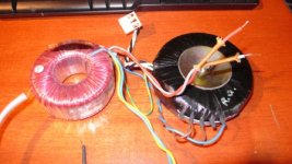
The A60 will have been designed such that, if driven hard, the PSU will collapse. This was a budget amp in the early 80s. If memory serves the transformer is only 120VA.
I think the transformer may be a bit bigger than that. Here's a picture of one next to a Creek CAS4040 transformer. The Creek is noted as 15-0-15/120VA. The only markings on the Holden & Fisher A60 transformer are 27-0-27. No rating. It feels substantially heavier too. Centre holes are the same size.The A60 will have been designed such that, if driven hard, the PSU will collapse. This was a budget amp in the early 80s. If memory serves the transformer is only 120VA.
Attachments
Jaycee,
I suspected that might be the case, hence my comment at the end.
Andrew,
By “low frequencies” I meant that beyond about a 4ms pulse response (250Hz) SOAR, (bit of a guess) the devices might survive (there is still Vceo to consider). It all depends on programme history, and assumes non repetitive signals (e.g. sine waves).
Brian.
A60 Distortion
Hi,
Sorry to hijack this thread, but thought someone might be able to shed some light on a problem i'm having with my A60.
Have been updating a late model A60. Have replaced all the electrolytics and transistors, including the TIP3055's. Put the amp on yesterday and was trilled to hear clean music. However, after about 15 minutes the left channel loses volume and starts to distort. If I turn the amp off for a while things return to normal, however after 15 minutes the problem resurfaces.
If I put the amp into mono mode both channels sound fine. I thought it might be the volume pot or one of the TIP 3055's, which I got off e-bay for my sins (have ordered new one's from Farnell today).
Advise very much welcome.
See if the DC conditions alter. Do the outputs get hot. Do any transistors get hotter than they should.
Check the polarity of all electroylitics. Don't rely on markings on the PCB, measure what is across each cap and see it's correct with regard to polarity.
Check all voltage ratings of caps are not exceeeded.
Check the polarity of all electroylitics. Don't rely on markings on the PCB, measure what is across each cap and see it's correct with regard to polarity.
Check all voltage ratings of caps are not exceeeded.
Thanks for the link, Mooly.
'Notice the output fuse. A tiny 1.5A, With all the protection, that seems overkill or rather it may be considered ineffective. Thermal distortion could still be an issue with 4-6R systems (very common today).
'Notice the output fuse. A tiny 1.5A, With all the protection, that seems overkill or rather it may be considered ineffective. Thermal distortion could still be an issue with 4-6R systems (very common today).

- Status
- Not open for further replies.
- Home
- Amplifiers
- Solid State
- A&R A60 SOA Removal