Hi
this is a practical problem I am unable to tackle.
I have algebraically figured the Impedance of a pole correcting network
to be
Z=R*(1+ Z1*(1/R1 + 1 /R2))
all constants are given.
Z1 is the parallel connection of a capacitor C with resistor R3 , this network in in series connection with a resistor R4. No problem so far as all constants are given Z can be calculated.
But what is the actual topology of the compensation network as resistors and capacitors? Most possibly I am just thinking along wrong way but I am unable to get a solution.
Thanks
Hi
this is a practical problem I am unable to tackle.
I have algebraically figured the Impedance of a pole correcting network
to be
Z=R*(1+ Z1*(1/R1 + 1 /R2))
all constants are given.
Z1 is the parallel connection of a capacitor C with resistor R3 , this network in in series connection with a resistor R4. No problem so far as all constants are given Z can be calculated.
But what is the actual topology of the compensation network as resistors and capacitors? Most possibly I am just thinking along wrong way but I am unable to get a solution.
Thanks
Please post your circuit. That would make it a lot easier to comment.
BTW:
Is it: Z=R*(1+ Z1*(1/R1 + 1 /R2))
Or is it: Z=R*(1+ Z1*((1/R1) + (1 /R2)))
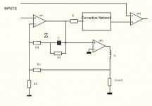
Thank you for asking. This is not the actual circuit but depicts the question. The network
denoted as Z consists of C,R3, and R4. Its purpose is to compensate a pole created by the feedback taken from a phase shifting device ( indicated by inductor). The corrective network ( inclusive of R) must have the impedance
Zc=R*(1+Z*((1/R1)+(1/R2))) and the question is that Zc can be calculated but how is it implemented?
Thanks
Dieter F
Attachments
Maybe I do not understand your circuit. But the Z-networks seems to
be without any effect as it is not loaded anyway. And connecting it to
the non-inverting input of OP2 would end up in a self oscillating stage.
To compensate a pole, it takes one zero, that is one resistor and one cap.
But your z-network includes one pole and and one zero.
be without any effect as it is not loaded anyway. And connecting it to
the non-inverting input of OP2 would end up in a self oscillating stage.
To compensate a pole, it takes one zero, that is one resistor and one cap.
But your z-network includes one pole and and one zero.
Yes the Z network compensates the pole introduced by the actual load.
This works ok. The desired compensation network results from additional upgrade of the actual circuit's functions. It is of course terminated by a resistor to ground at the noninverting input. It cannot be solved otherwise because of the space limitation of the PCB and its layout.
But the problem is not touched by this details. It is just how does one make a computed series Z impedance - basically a filter - into real components?
Dieter F.
- Status
- Not open for further replies.