Looking at supply for tube heaters and noodling around with possibilities in PSud , I hit something I've seen many times but never really understood.
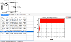
Shown here first sim is with a load calculated as 3.1A@12V =3.87Ω
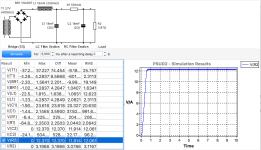
What I don't get is that while the ripple across the load centres at roughly 20V, the second sim with 0.1Ω resistance in the added filter nets a Vout so much lower.
3.1A through .1Ω is only 0.31V, why does the following capacitor pull it so much farther down?
Thanks
Shown here first sim is with a load calculated as 3.1A@12V =3.87Ω
What I don't get is that while the ripple across the load centres at roughly 20V, the second sim with 0.1Ω resistance in the added filter nets a Vout so much lower.
3.1A through .1Ω is only 0.31V, why does the following capacitor pull it so much farther down?
Thanks
Attachments
Last edited:
It might be easier for readers to understand the differences between the first sim and the second sim, if you showed them the second sim schematic and results.
Quirky results often arise from quirky setup of the values used in the sim - especially for the simpler sim program like PSUD2.
For example the 2 ohm ESR of an 18mF cap is 'unreal', especially in the context of a circuit being asked to pass amps of current, as the first filter cap has amps of ripple current, and that produces many volts across 2 ohms of ESR.
As an aside, you need to identify if you measured the winding resistances of the power transformer primary and secondary windings and used the PSUD2 calculator to arrive at 0.4 ohm. Similarly how did you determine the choke parameters? There are also other diode models available, and they include diodes with higher current rating than a 1N4007.
One more practical aspect is that the use of dc for heaters is mainly about suppressing heater Vac from say 6V down by an order of magnitude or so - so even 0.6Vac would be a likely significant improvement. Reducing Vac on the heaters down even further may just be aesthetic.
Last edited:

That's a choke input filter so probably in the first example, the combination of variables resulted in inductance below critical, so the supply acts more like a capacitor input.
trobbins ,
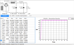
Thanks for that. I had forgotten to adjust the cap ESR and by lowering it to that of a Kemet on DIgikey - 0.009Ω , the result is shown.
The power transformer numbers were taken from an Amplimo datasheet and the choke's were from Hammond. Both these were arbitrary choices off websites as a starting point using real world values for planning a supply
In answer to your note about practical approach to heating, I've come up with a bench supply powered circuit I like that uses 2 DHT's , 1 IDHT and a Super Reg per stereo channel, and while I haven't yet tried AC on the IDHT , I'm sure the remaining three need DC.
The noodling is about getting a feel for where I might be able to take things for a one supply feeds all sort of approach, not that I really think it's possible, but at least to get it down from a max of 8 for a two channel rig.
Thanks.
Attachments
Last edited:
I think PSUD is getting it wrong - the second circuit is basically just double the capacitance, the 100mohm resistor has little influence, so the ripple voltage should halve. Either that or PSUD is simulating some non-linear effects?
Are you simulating at the right frequency though?
Are you simulating at the right frequency though?
The OP has addressed his initial concern.
Ripple across C1 is 0.16Vpp, dropping to 0.09Vpp across C2. The ripple is significantly influenced by the capacitor ESR, which is 9% of R1 on each side, so 'should halve' is not a good approximation. Imho, PSUD2 is doing a good job of allowing the OP to appreciate what his ripple may get to, as long as the model parameters and choice of diode model are adjusted to suit what he may end up using.
Ripple across C1 is 0.16Vpp, dropping to 0.09Vpp across C2. The ripple is significantly influenced by the capacitor ESR, which is 9% of R1 on each side, so 'should halve' is not a good approximation. Imho, PSUD2 is doing a good job of allowing the OP to appreciate what his ripple may get to, as long as the model parameters and choice of diode model are adjusted to suit what he may end up using.
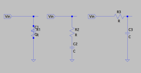
The one thing that seems counter-intuitive to me is that reducing ESR raises voltage. If the ESR is an impedance between plates/poles of the capacitor and one plate is at common then it's a resistance from the +Voltage rail to common. Looking at it that way I'd think the lower the resistance the more energy gets shunted to common. Obviously, I've got the whole concept of ESR completely wrong.
Is ESR simply sheet resistance?
Is ESR simply sheet resistance?
ESR is a power loss within a capacitor that passes ripple current. The choke and winding resistance of the PT also interact with the cap ESR. Play around with PSUD2 some more to get a better insight. Cap ESR also can vary, so there could be significant measured differences in ripple compare to what you anticipate by using datasheet maximums.
Yes. I never really turned to have a good look at it and was satisfied with a sort of vague image of "series" to mean what I'd call "in-line" with the capacitor on the leg of the circuit it was in. ie, like the first two in the attached image. I didn't understand it was a value for loss as in the third .
Thanks !
Thanks !
Attachments
- Home
- Amplifiers
- Power Supplies
- A question about the basics of PS filtering