Hello
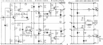
I repair that 55 watt power amp, replacing the driver by bd139 and bd140, and the output by mj15003 and mj15004.
I did adjust p5 the ofset, and p6 the bias are adjust to 75 ma.
My first tests few days ago was at quite low power output listening and sound ok at low output, but yesterday I did try it at more power and the power amp does cracking sound and distortions at 5 watt and more.
I did check all wires.
What can be the problems ?
I included the schematic of that amp.
Thank
Gaetan
Attachments
Contact problem in resistances use to produce this noise
Touch resistances...or hit them with a pencil.... this way you will be sure if there are contact problems.... with the amplifier on...you will listen the noises.
Sometimes the resistance seems to be perfect..but when you remove it you perceive that one of the leads can turn....loosen from the main body.
regards,
Carlos
Once i had those noises too...and were result of chemical reaction in the solder.
I do not know what the amplifier owner did with the boards that they were strange when you look to them.... solder had lost the bright.... and there were a coating... a varnish painted using brush over the board...bright material that alcohol was attacking.
The amplifier was noisy and poping too.... and i discover that something was wrong with that solder because when i have used the soldering iron it started to produce pops ...to make noises while the solder was melting.... was a hard work to substitute all that solder.
I used WD40 into the board to avoid hot solder to fix somewhere and i started with the solder heating the solder points and fast i passed the brush to remove them.... the remotion was complete...the brush was cuted short (the hairs) to be more compact and hard.... and the remotion of solder had to be fast.
Hard to explain the brush movements..was hitting and expulsive to left side at same time.
Then i have to solder each point to start to melt the next other one.
Hard work.... the board was cleaned using Kerozene (Jet aviation fuel) to remove the WD40 oil and left to dry exposed to sunlight and wind for half hour.
The guy had used varnish after he had used some chemical he could not explain what was that material.... the varnish was removed using Alcohol to start the re-soldering.
Beaucoup du travaile.
Now i have the word....wipe!...have to hit and wipe at the same time..solder is removed and made into small balls...they do not attach, do not glue into other solder points because oiled.
The amplifier turns silent again.
No problems Gaetan, my pleasure, vouz êtes mon ami..n'a pas du probléme avec mois.
regards,
Carlos
Hi Gaetan,
My! That schematic looks like an older amplifier.
I think that an oscilloscope would be very handy right about now. Do you have access to one?
-Chris
My! That schematic looks like an older amplifier.
I think that an oscilloscope would be very handy right about now. Do you have access to one?
-Chris
anatech said:Hi Gaetan,
My! That schematic looks like an older amplifier.
I think that an oscilloscope would be very handy right about now. Do you have access to one?
-Chris
Hello
Yes, quite old, about 30 years old Radford amp.
I have an old tube Telequipment scope but he is becoming unstable, any sine wave in that scope are vibrating. So it's now a disco scope... arghh
Gaetan
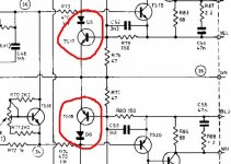
jaycee said:Check the transistors and diodes in the VI limiting circuit
Hello
Ok, D5 - D6 - TS16 - TS17, wen I repaired that amp I did need to replace one of those two transistor by an equivalence.
Thank
Gaetan
Attachments
Destroyer X wrote
I coated a board with french polish and it was behaving exactly similar.
Gajanan Phadte
... and i discover that something was wrong with that solder because when i have used the soldering iron it started to produce pops ..
I coated a board with french polish and it was behaving exactly similar.
Gajanan Phadte
jaycee said:Check the transistors and diodes in the VI limiting circuit
Hello
D5 - D6 are ok.
So, I disconected D5 - D6 - TS17 - TS18, and now it's working, I can goes to a clear 60 watt, my friend gone be happy to have his Radford back to life. I may not reconnect the the VI limiting circuit, since those protection circuit are not good for sonic quality.
Is it possible that the two transistor ts17 and ts18 of the VI limiting circuit need to matched ?
You was right on the spot jaycee.
Thank everybody.
Gaetan
Hi Gaetan,
No, they do not need matching.
Reconnect the circuit, but also replace the diodes. I have seen them go leaky, but still test okay with a meter.
-Chris
No, they do not need matching.
Reconnect the circuit, but also replace the diodes. I have seen them go leaky, but still test okay with a meter.
-Chris
anatech said:Hi Gaetan,
No, they do not need matching.
Reconnect the circuit, but also replace the diodes. I have seen them go leaky, but still test okay with a meter.
-Chris
Hello
Ok
The diodes are BAX16, any replacements number for them ?
Btw, that old Radford hd250 sound very nice.
Thank
Gaetan
Hi Gaetan,
I expect they are just little glass signal diodes? 1N4148 should do the trick on a guess.
-Chris
I expect they are just little glass signal diodes? 1N4148 should do the trick on a guess.
-Chris
1N4148 should do. Also, some small signal transistors like MPSA42/92 should do just fine as replacements for the VI limiter transistors - but check the pinout of the originals.
Hello
I did compared the amp channel with the connected VI limiting circuit, vs the amp channel who are not connected to the VI limiting circuit.
The channel who are not connected to the VI limiting circuit do have much more dynamic and clarity.
How about not connect the VI limiting circuit and just puting a fuse on the 70 volt line ? (a 8 amp fuse ?)
That 60 watt Radford amp sound excellent. I have also to say that it have a big regulated power supply.
Thank to everybody
Gaetan
Attachments

Hi Gaetan,
Anyone betting on my answer can now collect on that bet. 😉
You can try to back it off a little, but do not remove it.
-Chris
I do not recommend that.How about not connect the VI limiting circuit and just puting a fuse on the 70 volt line ? (a 8 amp fuse ?)
Anyone betting on my answer can now collect on that bet. 😉
You can try to back it off a little, but do not remove it.
-Chris
- Status
- Not open for further replies.
- Home
- Amplifiers
- Solid State
- A problem of cracking sound amp