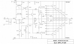
i am going to play with this amplifier in the next days i would like to have opinions about the schematic
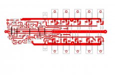
also i have allready made pcb and will be very ineteresting to have suggestions on how to stress the amplifier as much is possible for testing
allready i will perform all the known tests with a dummy load and so on and on but i would like to have more sugestions regarding tests with more or much more stress
( i have a big solenoid coil and i thought that since this a very reactive load like a speaker may i put this on the test also )
thank you very much
Attachments
Last edited:
some updates ( eventhough it seems that there is not much interest )
some more will also come the next few days ....
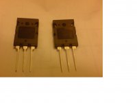
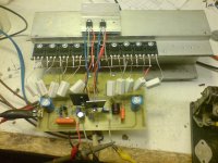
Just come in to my shop 1943 5200 labeled as 1K26AA A1943 and 1K48AB C5200 from FAIRCHILD ... by the looks it seems that is an excellent product will see the next few coming days
ok ...working with the fairchild transitors seem that base resistors are not needed amplifier operates way much better and cooler with out them ....
Emmiter resistors i used 0R39 since this was only available in my shop
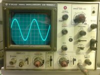
biassed the all thing arround 90ma and made some tests in 68 and 78 volt rails ...with 78 volt rails i get about 50 volts in the output and amp works perfect for a very good bandwidth and also square wave starts to get round just about 20khz fairly good i thing for a thing like that so simply made
take a look at the tranistors
some more will also come the next few days ....
Just come in to my shop 1943 5200 labeled as 1K26AA A1943 and 1K48AB C5200 from FAIRCHILD ... by the looks it seems that is an excellent product will see the next few coming days
ok ...working with the fairchild transitors seem that base resistors are not needed amplifier operates way much better and cooler with out them ....
Emmiter resistors i used 0R39 since this was only available in my shop
biassed the all thing arround 90ma and made some tests in 68 and 78 volt rails ...with 78 volt rails i get about 50 volts in the output and amp works perfect for a very good bandwidth and also square wave starts to get round just about 20khz fairly good i thing for a thing like that so simply made
take a look at the tranistors
Attachments

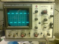
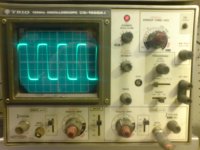
construction mess ....and 1khz signal just before cliping ...meanwhile and as we speak various tests have been done and for starts all is running very cool ...so lets see ...
there is a lot more to be done
there is a lot more to be done
Attachments
for this circuit the VI limmiter is not ready made yet in the next few days we will come to that also .....
given thwe oportunity and in any case somebody is reading this there is something to state and i would like to listen comments please .
In the forum there is a practice regarding number of outputs versus rail voltage to be calculated from the soar plots of the given transitors ....
there is ofcourse other ways to do it only thing you have to do is take a look at the comercial approach existing everywhere and mostly in the Japanese market or philosophy
the story is very simple .... just put a couple of transitors with 50+50 or 60+60 volt rails and limmit the current that flows from them with the vi limmiter
now i can listen to a lot of things of what is right or wrong but lets face it this was the Japanese approach ages now ...
Amplifier that has 50 volts output is a PA amplifier and a VI limmiter is a must and a fact
so ...opinion have to be given taken all the above as a fact ....
thanks for your time ...
regards sakis
Last edited:
yes you are right ...i was also amazed by it cause normally amplifiers on testing state like this one and especially while using 60 cm of rail cable and generally messed up wiring usually loop even if you breath next to them ...
i expect it to perform better when cased ( together with my power supply that forum rules will not allow to post )
i expect it to perform better when cased ( together with my power supply that forum rules will not allow to post )
Last edited:
Only useful contribution I can make - consider an LED instead of 2x1n4148, and either dont share this between LTP current sink and VAS current sink, or put in a 1K base resistor at the VAS current sink to avoid problems with clipping.
it seems that i get some feedback regarding the VAs area and thatthis one will be loaded at clip conditions and generally have quite a lot of stress driving 10 transitors ...
will make some other testings and check that also
will make some other testings and check that also
The bias circuit looks dodgy with the way the pot is wired.
If the wiper goesopen the bias with increase and blow up the output transistors.
Look around for a better bias circuit that is fail safe.
If the wiper goesopen the bias with increase and blow up the output transistors.
Look around for a better bias circuit that is fail safe.
the MJE for the VAS could be bettered.
The output protection is I only. An extra resistor is needed to convert it to IV.
If the protection triggers it will draw too much current through the VAS and may blow it. That might be why they have chosen the wrong transistor, to stop it blowing up.
If you change the VAS to a low Cob type (eg 2sa1360) then you must fit protection to the VAS. Leach details it in Lo Tim.
Are the DC blocking capacitors 2u2F (2M2F) and 100uF (100mF)?
Last edited:
VI limmiter is not ready yet ...it is in the schematic as an indication ....it will be configured in the next days
then again i will take in mind your comment regarding the combination of protection and vas
thanks Andrew
then again i will take in mind your comment regarding the combination of protection and vas
thanks Andrew
some small updates .....
i used the amp for the all weekend ....abused it in many possible ways .... used it with both low grade and high grade power supply ( one that voltage dives at full load and other that looses very litle when loaded )
still all the above is done without vi LIMITER
temperatures are very good here and there
still the bias sceme needs to be redesigned , still Vi limiter has to be designed , and then more tests have to be done based on AndrewT comment IE short circuit condition and or VI limiter active versus load to VAS
coming up in a few days
regards sakis
Sakis
Replace this beast MJE340 used as Vbe multiplier with a BD137. A BJT of low Vce is more sensitive in thermal variations than a BJT of high Vce. Thus you will have better management of Iq.
Fotis
Replace this beast MJE340 used as Vbe multiplier with a BD137. A BJT of low Vce is more sensitive in thermal variations than a BJT of high Vce. Thus you will have better management of Iq.
Fotis
Last edited:
thanks fotios .... good to see you here ... this generic ...there is a lot to be done as we speak i listen to all comments and will make tests with or with out ...
thanks .... hope you are doing fine leventi !!!!
thanks .... hope you are doing fine leventi !!!!
- Status
- Not open for further replies.
- Home
- Amplifiers
- Solid State
- A ...power amplifier