Wouldn't you need measured data from a large population of Store Kit NP 2022 FE units, to draw conclusions? This one unit might be +2 (or -2) standard deviations from the mean, and you'd never know it.
Revised pcb allows DC offset adjustment, but you will likely find some trade off between that and lowest distortion.
Also slight improvement with degenerating resistor on pnp emitter.
Also slight improvement with degenerating resistor on pnp emitter.
Unfortunately, only very few DIYERs on this forum have reported their findings.Wouldn't you need measured data from a large..............
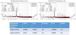
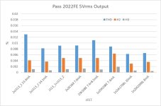
Now it is the fun part. I measured the FE. At first, it is the channel with J113 23.4mA Idss. THD, H2, H3 and H2/H3 at 5Vrms and 10Vrms output. The results are in the same order I found in the forum.
At lower output level it is H2 dominant. Near 10V it changes to H3 dominant.
At lower output level it is H2 dominant. Near 10V it changes to H3 dominant.
Attachments

From the previous Posts #1-7, I simulated extensively the effect of combining Jfets with different Idss in Q1 and Q2. I put the quote here.
THD is between above two conjurations. But it has the max H2.
From the measurement, there could be two advantages to combine different JFETs in practice:
1. it is much easier to find two quads of JFETS than one octet.
2. it could add more sugar in the FE to sweeten sound.
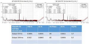
I mixed J113 with 23.4 and 24.1 mA Idss as Q1 and Q2. The trend matches very well with the simulation. The phase of H2 is more than 80, which is very close to 90.Pass original FE 2022, CCS same, change one J113 to J112, R6 value to get comparable DC offset at output. Total THD increased, but it is H2, H3 decreased.
THD is between above two conjurations. But it has the max H2.
From the measurement, there could be two advantages to combine different JFETs in practice:
1. it is much easier to find two quads of JFETS than one octet.
2. it could add more sugar in the FE to sweeten sound.
Attachments
Last edited:
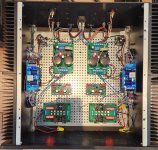
My DIY FE 2022 was with the Store JFETs, low cost no name resistors, V+ = 62V. Description here: My DIY FE 2022 build
I did some FFT measurements and the 5Vrms THD was lower and the 10Vrms THD was substantially lower: My DIY FE 2022 FFTs
Here is Nelson's Distortion vs Output chart from his article (Vout may possibly be Vp but I am not sure as I do not have an AP):

I did some FFT measurements and the 5Vrms THD was lower and the 10Vrms THD was substantially lower: My DIY FE 2022 FFTs
Here is Nelson's Distortion vs Output chart from his article (Vout may possibly be Vp but I am not sure as I do not have an AP):
Last edited:
I use Focusrite Scarlett Solo and its own signal generator. The loopback THD is in the order 0.002-0.005%.
Do you have a better signal generator with lower THD.
Or yours have much higher supply voltage so the better overhead for the higher output.
Just guess.
But I see one thing we are common. The FE become H3 dominant near 10Vrms output.
Do you have a better signal generator with lower THD.
Or yours have much higher supply voltage so the better overhead for the higher output.
Just guess.
But I see one thing we are common. The FE become H3 dominant near 10Vrms output.
Last edited:
Although I use a higher V+, Nelson's measurements were with the standard voltage, and my measurements at higher output levels were in line with his.
I have a Gen 2 Scarlett 2i2 and I had measured its THD at less than 0.001%. I use an older Victor oscillator, which also measured at less than 0.001% THD, for my measurements of the DIY FE 2022.
You could check your Scarlett Solo at various output voltages to see if the THD rises substantially with voltage output. Your loopback distortion appears high though, at least compared to my 2i2.
I am not sure whether the bump in V+ lowered the distortion. The intent with the higher V+ was to extend the output voltage. I did some simulations and they showed an increase in distortion with increased V+. I did not build and measure at V+=50V.
I use +/-18VDC as power supply. If the output is 10Vrms, the peak is 14.1V. Also considering the voltage drop on R10 and R8, the Vds on Q4 would be reduced to 2V. Could this be the one reason for higher THD?
The power supply voltage does matter.
The only way that I know of to check your build against Nelson's design is to power it with the voltage that Nelson used in his design. If you do that and the results are substantially different from Nelson's, then the difference may be due to your circuit/components and/or your measurement method/setup.
The only way that I know of to check your build against Nelson's design is to power it with the voltage that Nelson used in his design. If you do that and the results are substantially different from Nelson's, then the difference may be due to your circuit/components and/or your measurement method/setup.
The circuit/components are from the store except changing one J113.
The measurement method/setup might be the reason.
The measurement method/setup might be the reason.

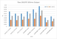
Tried few JFets for the input.
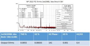
From the view of THD, Toshiba 2SK170BL is still the best piece, even single one. 2x2SK209BL comes very close. They are the second best, but some effort is needed here.
Whatever are put in front, they have same trend, near 10Vrms output, the distortion becomes H3 dominant.
From the view of THD, Toshiba 2SK170BL is still the best piece, even single one. 2x2SK209BL comes very close. They are the second best, but some effort is needed here.
Whatever are put in front, they have same trend, near 10Vrms output, the distortion becomes H3 dominant.
Attachments

Hello wwwtttwww,
excellent work and information!
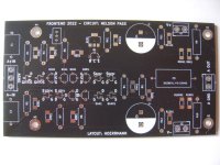
I am on a similar route with frontend 2022... I made my 3rd version of a pcb - all TO-92 and SMD footprints for the JFets doubled up.
Also doubled positions for THT and SMD-resistors for flexibilty - what will be available... But the pcb got much bigger and slightly longer traces.
I am stuffing one pair of pcbs with Toshiba 2SK170. Will later continue with the 2SK209 BL or GR.
Greets
Dirk
excellent work and information!
I am on a similar route with frontend 2022... I made my 3rd version of a pcb - all TO-92 and SMD footprints for the JFets doubled up.
Also doubled positions for THT and SMD-resistors for flexibilty - what will be available... But the pcb got much bigger and slightly longer traces.
I am stuffing one pair of pcbs with Toshiba 2SK170. Will later continue with the 2SK209 BL or GR.
Greets
Dirk
Attachments
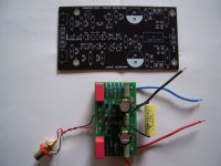
I built my own 2x2SK209BL module. Pins are compatible with TO-92 kinked legs. So the PCB can be similar.
Attachments
Last edited:
Could we make a little improvement on the FE at higher output?
From the previous tests, the FE becomes H3 dominant regardless what JFets we put in front. Increasing power supply voltage does not seem to help.
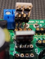
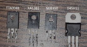
After I saw Mr. Pass teased his FE design in a video, I thought the Q5 could have TO126 or TO220 package. So I bought 4 common VAS transistors KA1381, MJE350, TTA004B and D45H11. But it came out with KA992.
Anyway, I wanted to give a try.
From the previous tests, the FE becomes H3 dominant regardless what JFets we put in front. Increasing power supply voltage does not seem to help.
After I saw Mr. Pass teased his FE design in a video, I thought the Q5 could have TO126 or TO220 package. So I bought 4 common VAS transistors KA1381, MJE350, TTA004B and D45H11. But it came out with KA992.
Anyway, I wanted to give a try.
Attachments
- Home
- Amplifiers
- Pass Labs
- A possible new method to enhance the enjoyment of Pass FE2022