2SK246Y CCS
dwjames,
Those are great values. My first CCS uses 2SK246Y with an Idss of about 2.0ma. Plenty of voltage drop across the 2SK246Y for constant current regulation. The 2.2ma pair should work great also.
nige2000,
I put a strong test signal through my 2SK246Y JFETs for 50 hours before soldering them into my DDDAC. I like the 2SK246Y sq quality better than the 2SK170 which sounded a bit too bright for me. With the 1/2 clock delay circuit and 2SK246Y CCS in addition to all my Vregs and Buffer - the sound stage is incredible with silent space between the instruments. On one recording the support choral group is located to my right and slightly behind me - wow! Detail seems unlimited, but the musical presentation is also relaxed and balanced. My DDDAC seems to have it all. I wish I could put this sound in a bottle and send some to every one of you.
I agree that the 2SK170 and 2SK246 have a different sound character with the 2SK170 having the most musical energy. With the buffer providing more musical authority and detail I had to dial back the CCS brightness a bit with the 2SK246. I also find the 2SK246 to be very articulate and unfatiguing. The 2SK246 has a small negative temperature coefficient making it suitable for warm multiple DAC stacks. The 2SK170 has a huge positive temperature coefficient that is about 10 times larger than for the 2SK246 which makes it difficult to maintain the desired current for warm DAC installations.
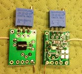
Below is a pic of my 2SK246 CCS boards before I installed them. The white wires go to ground. These boards can accommodate a wide variety of component orientations and board positions depending on the installation. It can also hold components for cascoding, but this seems less necessary now. The picture shows 1k SMD resistors and 2K pots which are the parts I had lying around. I will order 1.5K SMD resistors and 1K pots for my next set of CCS.
dwjames,
Those are great values. My first CCS uses 2SK246Y with an Idss of about 2.0ma. Plenty of voltage drop across the 2SK246Y for constant current regulation. The 2.2ma pair should work great also.
nige2000,
I put a strong test signal through my 2SK246Y JFETs for 50 hours before soldering them into my DDDAC. I like the 2SK246Y sq quality better than the 2SK170 which sounded a bit too bright for me. With the 1/2 clock delay circuit and 2SK246Y CCS in addition to all my Vregs and Buffer - the sound stage is incredible with silent space between the instruments. On one recording the support choral group is located to my right and slightly behind me - wow! Detail seems unlimited, but the musical presentation is also relaxed and balanced. My DDDAC seems to have it all. I wish I could put this sound in a bottle and send some to every one of you.
I agree that the 2SK170 and 2SK246 have a different sound character with the 2SK170 having the most musical energy. With the buffer providing more musical authority and detail I had to dial back the CCS brightness a bit with the 2SK246. I also find the 2SK246 to be very articulate and unfatiguing. The 2SK246 has a small negative temperature coefficient making it suitable for warm multiple DAC stacks. The 2SK170 has a huge positive temperature coefficient that is about 10 times larger than for the 2SK246 which makes it difficult to maintain the desired current for warm DAC installations.
Below is a pic of my 2SK246 CCS boards before I installed them. The white wires go to ground. These boards can accommodate a wide variety of component orientations and board positions depending on the installation. It can also hold components for cascoding, but this seems less necessary now. The picture shows 1k SMD resistors and 2K pots which are the parts I had lying around. I will order 1.5K SMD resistors and 1K pots for my next set of CCS.
Attachments
Last edited:
On a .......
Many thanks guys! I have received reponse from Lucian, he is happy to replace the faulty chip for me free of charge provided that I pay for shipping cost forth and back, and the replacement chip. According to him, this isn't the first and he has admitted his poor judgement on chip selection based on manufacture recommendation. I check out the freight cost, $30 each way. So the total cost fixing this is approx $70. Might as well get a new usb to I2S board from JLsound with better clocking at approx US$70.Could be as simple as a dry joint under the usb socket? Have you tried to reflow/resolder these yet?.
I wonder if we could teach an old dog new tricks? Experience showed it can be extremely challenging! 😀Today I give a call to Guido asking about my order... I also explain to him that many of us in the forum are really upset about his way to deal with us as customers. He recognize his lack of communication and he give me his apologize... I hope was not just kind words.
Regards,
Enrico
Guys I have an issue with my DDDAC I need to get sorted out.
Initially the following was happening once every several weeks, but that turned into once every several days. What’s happening is that once every so often I get a continues loud "white noise" coming from the dac, either/or a random (in time) loud static crackling noise. (could be two different issues)
The issue seems to remedy itself by turning the amp off/on (once or several times).. But since I don’t know what’s going on I’ve not been able to troubleshoot it properly, as I don’t want to keep the dac running in this (error) state.
I’ve contacted Lucien from WaveIO, and he didn’t have any idea, and started pointing at the USB cable, which I’ve swapped out, which made no difference.. (Could still be a socket issue)
In all cases below my transport (Mac mini), is always up and running before I switch the dac on..
Some senario’s have crossed my mind.
1. There could be a slight power up time difference between the WaveIO and DDDAC, which trips something on I2S interface into an error state. (Doede, can you comment on this?)
2. A intermittend hardware fault developing either on the DDDAC, mainboard, dac boards or WaveIO.
3. A USB interface issue. What would happen if, for example, the USB interface sensed GND/+5V but no D+ or D-?
Any clues?
Last edited:
Could you try swapping to a Raspberry Pi and using direct i2s in for a bit?Guys I have an issue with my DDDAC I need to get sorted out.
That would let you split the potential sources of problem in half and see whether it's a usb/WaveIO issue or a DDDAC issue
Thanks James. I don't have a different i2s (Rpi) feed to test with. Next time I will switch to SPDIF input, which would bypass the WaveIO, see if that makes a difference.
USB converter
Guys I have an issue with my DDDAC I need to get sorted out.
Initially the following was happening once every several weeks, but that turned into once every several days. What’s happening is that once every so often I get a continues loud "white noise" coming from the dac, either/or a random (in time) loud static crackling noise. (could be two different issues)
Hi Stijn.
Be sure the reg you feed the WaveIO with delivers at least 400mAmps, under all conditions.
To confirm, try another (lab)reg.
Success,
Ed
the waveio consumes like 440mA. min 500mA would be good
Hi Stijn,
Among us all, you seem to be the only one is using Oscon at VCom and report first case abnormality. Is it worth trying the swap to Muse or Silmic 2?
Chanh
Among us all, you seem to be the only one is using Oscon at VCom and report first case abnormality. Is it worth trying the swap to Muse or Silmic 2?
Chanh
Thanks, the ps's I'm using for the WaveIO support up to 1 Amp @5V, so should ample, and several others are using them too..
Have you experienced these symptomes as a result of an insufficient PS?
Last edited:
Hi Chanh, thanks. Sorry but I'm not the only one using them and I can not logically infer your comment. They have the same electrical specification, as per design..
Hi Stijn,Hi Chanh, thanks. Sorry but I'm not the only one using them and I can not logically infer your comment. They have the same electrical specification, as per design..
It was a quick brainstorm through a process of elimination, I reaslised there is no logic to it. 🙂
Btw, I did have the 'White noise' experience when played around with my Raspberry Pi I2S connection to Mainboard. It turned out a loose i2s connection on mainboard. Could this be the delay circuitry on Mainboard? Again, only a thought. 🙂
Hope you get it solved soon!
crackling/noise
Hi Stijn,
Yes I did. It appeared to be a bad connection in my reg. A T.P. shunt reg.
Could not identify the problem clearly. After checking with a 2Amps desk lab. supply the problem was clear. In case of insufficient current, your computer could not even identify the USB soundcard, every now and than.
Ed
Thanks, the ps's I'm using for the WaveIO support up to 1 Amp @5V, so should ample, and several others are using them too..
Have you experienced these symptomes as a result of an insufficient PS?
Hi Stijn,
Yes I did. It appeared to be a bad connection in my reg. A T.P. shunt reg.
Could not identify the problem clearly. After checking with a 2Amps desk lab. supply the problem was clear. In case of insufficient current, your computer could not even identify the USB soundcard, every now and than.
Ed
Chanh,
Was not aware of the I2S board you mentioned so I looked for it.
I see the price at 77 euros. A bit more than 70 dollars.
Truly one of the most confusing websites I have ever seen.
What is it supposed to do better than Wave IO? Looks very similar, as if that means anything.
Was not aware of the I2S board you mentioned so I looked for it.
I see the price at 77 euros. A bit more than 70 dollars.
Truly one of the most confusing websites I have ever seen.
What is it supposed to do better than Wave IO? Looks very similar, as if that means anything.
Hi Rick,
The JLSounds USB to I2S was recommended to me as alternative replacement to my half faulty WaveIO. I've no experience with it but see they use better clocks and at 45.xx/49.xxMhz. I was told it is recommended by ZenElectro.
Btw, my WaveIO has the USB Multiplex chip fried one channel, hence the chip need replaced for onboard usb socket to work. I might need to engage a local technician for this if the labour isn't too costly? Hopefully, Lucian will send me the replacement chip or I could source one online!
Cheers,
Chanh
Last edited:
I had a problem with my Wave IO and sent it back to Lucian.
He is a fine fellow. I really like him.
But that postage expense is quite surprising.
I got some LENCO parts from a fellow in New Zealand many years ago and was surprised how inexpensive it was to ship by post. It ended up being delivered by DHL to me at a cost one-third of what DHL would have quoted.
When I sent my board back (from the US) I think the cost was about fifteen dollars, even less coming back from Romania.
Wanted to be sure you had looked at all of your options. Was the cost you mentioned for the Post Office or another carrier?
For tonight's entertainment, I had a quick ponder over these

A cross reference of Nige's clock delay mod drawings, Doede's schematic for the blue mainboard and Ross's excellent pictures of his tidy solution. Thanks guys for the guidance 🙂 I redrew it (badly) which helped get my head around what's doing what, then I got my iron out and made this little fellow.


It's not quite finished as the 100r resistor for the bck line isn't here yet. It's far from my finest work.... but everything's connected where it should be and nothing's connected where it shouldn't be so in theory we're good.
Should know for sure soon enough 🙂
A cross reference of Nige's clock delay mod drawings, Doede's schematic for the blue mainboard and Ross's excellent pictures of his tidy solution. Thanks guys for the guidance 🙂 I redrew it (badly) which helped get my head around what's doing what, then I got my iron out and made this little fellow.
It's not quite finished as the 100r resistor for the bck line isn't here yet. It's far from my finest work.... but everything's connected where it should be and nothing's connected where it shouldn't be so in theory we're good.
Should know for sure soon enough 🙂
Whilst I'm doing this clock delay mod, is there any necessity or benefit to changing the 3.3v regulator on the main board for a 5v one?
It's easily done as the one I've used has jumpers to adjust the voltage.
Cheers,
James
It's easily done as the one I've used has jumpers to adjust the voltage.
Cheers,
James
dwjames,
First replace the 1000 ohm resistors for R7 and R9 with 100 ohms to get rid of the slight delay caused by the 1000 ohm resistor. I think that NOT doing this with my initial test with 3.3Volts is what caused a negative first impression.
Try the 1/2 chip delay first with the 3.3V Vreg setting. After the circuit WORKS and you listen to some familiar recordings then switch your Vreg to 5.0 volts. The 2 chip circuit adds almost no extra load to the Vreg. According to the data sheets the 74VHCxxxx chips switch state much more quickly when operating at 5.0 volts.
I am eager to read your impression of any difference in sq you can hear from adding the circuit and does 5.0 volts give any more improvement?
My engineering mind cannot figure out why new components, circuits, PS, etc in the digital domain of 1's and 0's have to go through a burnin period, but my ears tell me this is necessary. Anyone want to pontificate on this?
- Home
- Source & Line
- Digital Line Level
- A NOS 192/24 DAC with the PCM1794 (and WaveIO USB input)