Hello,
A few pictures of a little something I have been working on. It now works too, which is a real bonus - just needs a lid and some sides.
Based on the Silicon Chip 15W design of about 10 years ago. Everything has been upgraded (especially heatsinks) it is probably good for 18-20W.
Monoblock with separate power supply for each channel.
I was hoping this would cure my nasty case of DIY-itis, but it seems to have only made things worse....
Attachments
Member
Joined 2009
Paid Member
Great looking construction, very neat and tidy. The regulated PSU is a sight to behold, a good use of multiple parallel capacitors for low ESR etc.
I'm working on a simple Zen-type DIY design and your photos give me some inspiration - can you post more details (or is this commercial 'Owl Audio' pcb ?)
I'm working on a simple Zen-type DIY design and your photos give me some inspiration - can you post more details (or is this commercial 'Owl Audio' pcb ?)
Last edited:
Owl Audio is something I wanted to take places - realistically I don't think it will ever leave my workshop! I think staying really small is the best way to make sure DIY is still fun....I don't really have the technical know how to design from scratch - hence the SC base.
A couple of details on the project -
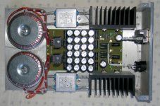
Power supply PCB is 3oz single sided;
2 x 120VA toroids per channel each with a mains filter;
Rectifiers are ordinary slow types with 1nF snubbers;
24 x Panasonic 2700uF bypassed with 8 x Solen 0.1uF for main capacitance and
LM317 and LM337 regulators on lots of heatsinking.
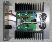
Amplifier - PCB is 2oz double sided, star earthed;
RCA andbinding posts are Vampire;
Input cap is 3.3uF Solen SB;
Input filter and feedback network resistor are bulk foil;
Feedback capcitor is bi-polar black gate;
Quiescent current trimmer is a stupidly expensive bulk foil unit;
2 x 4700uF Cerafines to boost filter caps on each amplifier;
Rubycon ZLH filter caps on the board, bypassed with WIMA,
Other resitors are Welwynn RC55 0.05%;
Small signal transitors are BC550 and BC560 all matched to <1% and
Driver transitors are Sanken 2SA1494 and 2SC3858.
Sounds good too.
A couple of details on the project -
Power supply PCB is 3oz single sided;
2 x 120VA toroids per channel each with a mains filter;
Rectifiers are ordinary slow types with 1nF snubbers;
24 x Panasonic 2700uF bypassed with 8 x Solen 0.1uF for main capacitance and
LM317 and LM337 regulators on lots of heatsinking.
Amplifier - PCB is 2oz double sided, star earthed;
RCA andbinding posts are Vampire;
Input cap is 3.3uF Solen SB;
Input filter and feedback network resistor are bulk foil;
Feedback capcitor is bi-polar black gate;
Quiescent current trimmer is a stupidly expensive bulk foil unit;
2 x 4700uF Cerafines to boost filter caps on each amplifier;
Rubycon ZLH filter caps on the board, bypassed with WIMA,
Other resitors are Welwynn RC55 0.05%;
Small signal transitors are BC550 and BC560 all matched to <1% and
Driver transitors are Sanken 2SA1494 and 2SC3858.
Sounds good too.
Member
Joined 2009
Paid Member

- Status
- This old topic is closed. If you want to reopen this topic, contact a moderator using the "Report Post" button.
- Home
- Amplifiers
- Solid State
- A nice warm 15W class A