I didn´t know that it´s such an issue to get MAT´s in the US!
You can get MAT02 in US for a whooping $22.24 each from Nxxxxk Electronics. (Don't know if it's allowed to post distributor name here?)

d1 parts
Hi list,
I am looking for good opportunities to buy:
1. 11.2896 Mhz Osci.
2. 2*7.5V / 36 VA Transformer
in Germany.
Please let me know.
Thanks
F
Hi list,
I am looking for good opportunities to buy:
1. 11.2896 Mhz Osci.
2. 2*7.5V / 36 VA Transformer
in Germany.
Please let me know.
Thanks
F
I got my 11.2896 Mhz crystals from Elso.
For the transformer, 2*6V should work even better, because of less heat from
the regulators.
-Peter
For the transformer, 2*6V should work even better, because of less heat from
the regulators.
-Peter
Hello Paolo, I would be interested in this project. Is the board a stereo DAC or would I need two of them for Stereo? Can the I2s output from a CDPRO2 Philips Drive be fed into this DAC?
Anthony
Anthony
Trying to improve an SACD 1000
I am looking at the D1 design and it looks to be a perfect design to replace the HDAM based analog stuff in that player. What would i need to do to make the design work off of +-12V supplies?
dee
;-D
I am looking at the D1 design and it looks to be a perfect design to replace the HDAM based analog stuff in that player. What would i need to do to make the design work off of +-12V supplies?
dee
;-D
Re: Trying to improve an SACD 1000
The D1 output stage wouldn't run from 12V supplies and cannot easily be changed to work from rails that low. The changes necessary would include changes in topology and/or swapping the FETs with BJTs.
I think installting an extra power supply in your CD player is the best way.
Penguin said:I am looking at the D1 design and it looks to be a perfect design to replace the HDAM based analog stuff in that player. What would i need to do to make the design work off of +-12V supplies?
The D1 output stage wouldn't run from 12V supplies and cannot easily be changed to work from rails that low. The changes necessary would include changes in topology and/or swapping the FETs with BJTs.
I think installting an extra power supply in your CD player is the best way.
AMT Freak do you have an email. I would like to ask you something about AMT drivers.
You can email me at promitheus@web.de
You can email me at promitheus@web.de
Thanks
Hi AMT,
I need to see if there is enough room in the SACD 1000 to do this. The player has CS 4397 DACS which put out balanced audio. Would the design tolarete the 2.26V DC offset coming out of the DAC or do i need to decouple with a CAP. Also can one increase the input impedance to say 470K to reduce the size of the cap needed?
dee
;-D
Ps image of the DAC circuitry in the SACD 1000 is on my ftp site
ftp://ftp.charm.net/pub/usr/home2/dcsipo/SACD 1000 DAC.jpgDAC Circuitry in the SACD 1000
Hi AMT,
The D1 output stage wouldn't run from 12V supplies and cannot easily be changed to work from rails that low. The changes necessary would include changes in topology and/or swapping the FETs with BJTs.
I need to see if there is enough room in the SACD 1000 to do this. The player has CS 4397 DACS which put out balanced audio. Would the design tolarete the 2.26V DC offset coming out of the DAC or do i need to decouple with a CAP. Also can one increase the input impedance to say 470K to reduce the size of the cap needed?
dee
;-D
Ps image of the DAC circuitry in the SACD 1000 is on my ftp site
ftp://ftp.charm.net/pub/usr/home2/dcsipo/SACD 1000 DAC.jpgDAC Circuitry in the SACD 1000
Re: Thanks
As far as I know, the CS4397 is a voltage output DAC, whereas the Pass D1 circuit basically is a cascode stage with current input... The good news is you can forget about the supply voltage problem 😉
Penguin said:The player has CS 4397 DACS which put out balanced audio. Would the design tolarete the 2.26V DC offset coming out of the DAC or do i need to decouple with a CAP.
As far as I know, the CS4397 is a voltage output DAC, whereas the Pass D1 circuit basically is a cascode stage with current input... The good news is you can forget about the supply voltage problem 😉
So in that case how do i deal; with the bad news?
Is there an X based design that would work with the CS 4397?
dee
;-D
Is there an X based design that would work with the CS 4397?
dee
;-D
Penguin
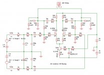
At the moment I am building an X-based analog outputstage as attaced for my Onkyo DX706 with SM5861 chip which has a voltage output with a DC offset at 2.4V, almost like yours. I don´t know if I can use the filtered balanced output at C7 and C9 to feed both the + and - inputs at the diff. pair or I have to ground R22 and disconnetct C7. Time will tell.
At the moment I am building an X-based analog outputstage as attaced for my Onkyo DX706 with SM5861 chip which has a voltage output with a DC offset at 2.4V, almost like yours. I don´t know if I can use the filtered balanced output at C7 and C9 to feed both the + and - inputs at the diff. pair or I have to ground R22 and disconnetct C7. Time will tell.
Attachments
Hi all,
Unfortunately, this interesting thread is going to die...
"Hi sparhawk,
The circuit is shown on first or 2nd page of this thread.
I´m working on X-ing it now, I´ll post it asap.
Uli "
I would be interested in the new results of Uli (hating signal caps, too. May exist simplier ways as well - w/o MATs - to realise the D1 dream?). After all, reading Stefano's experiences with Sony, this would be the general - high end! - solution for mass of DIYers.
And thanks to you all for your "open source intelligence"!
Laci
I hope this thread doesn't die...
Uli, any luck on converting the DAC to X topology?
Also, any word on making this into a PCB for purchase again?
If this were combined with the ongoing remote volume control project thread, you'd have quite the winner imo...
Uli, any luck on converting the DAC to X topology?
Also, any word on making this into a PCB for purchase again?
If this were combined with the ongoing remote volume control project thread, you'd have quite the winner imo...
The gauntlet has been raised...
Perhaps, Craig and I will take a crack at it. First, we have a lot of work to finish up the remote kit. We have talked about it...
Dale
Perhaps, Craig and I will take a crack at it. First, we have a lot of work to finish up the remote kit. We have talked about it...
Dale
harvardian said:The gauntlet has been raised...
Perhaps, Craig and I will take a crack at it. First, we have a lot of work to finish up the remote kit. We have talked about it...
Dale


maybe I will do a second version later this Year. With error corrections and improvements, but basically the same concept.
Peter,
You continue thinking to make a new PCB?
WEISS dac output sch is aleph
An externally hosted image should be here but it was not working when we last tested it.
That is a really nice topology. Do you have any more info such as schematic/layout.
Perhaps as a kit for or just the PCB?
Which DAC does it use etc etc
Ralph
Perhaps as a kit for or just the PCB?
Which DAC does it use etc etc
Ralph
At the very bottom of the image, just to the left of center is an AD797, only it has black text on a white background. I've never seen that before. Does it indicate anything significant?
Adrian
Adrian
- Status
- Not open for further replies.
- Home
- Amplifiers
- Pass Labs
- A nice dac to complement the Aleph-X.