maravedis, yes it does seem you are a little uninformed, while the output is still current, the length, impedance matching and grounding of the paths is vital (made even more difficult by airwiring as no proper ground plane is possible), no its not a complex circuit (although 4 or 8 times this circuit is). the sheer physical size needed to do what you are planning to do, will mean that the current paths are very long and for some of the outputs more than others. no amount of neatness will save you here, its a numbers game and we are not talking just subjective benefits, but rather very tangible objective measurements too. just the task of matching all the fets will not be insignificant, although someone has done that for you.... hehe
Last edited:
Zero ... 🙁
Gents,
Ok ... two of you want it .... first come first serve is the fairest way .
I had one email . I sent payment details and asked for postal address ,but no reply .
I spent a few hours at the weekend fielding questions . I don't wish to be rude ,but I don't want to run around like a chicken with its head cut off for 30 quid . I have just had a double hip - replacement so going to the post office is more than a little effort .
respectfully , Rich
maravedis:
Just to be clear, are you planning to pull 4 channels off a buffalo III or 8? At one point you mentioned getting a second BIII for multichannel, so I just want to be clear as to how many channels you plan to build, and how many channels each Buffalo will run. If you're only using four channels per BIII then you'll have more current for each channel.
As for P2P wiring off a heatsink, it'll be a challenge, but I wouldn't call it impossible. You'll need to mount all the fets very close together in pairs just below the DAC, and you'll need to put priority on keeping the wires from the DAC outputs to the I/V inputs very short. This would be pretty straightforward with 4 channels off a BIII, but it'll be a serious challenge with 8 channels.
I'd suggest using around 30V on the standard circuit for a dissipation of about 10W per channel. that would give you a reasonable total dissipation without giving up much performance.
I've attached the NTD1 LTSpice file, so have a go at it and learn how the whole thing works. It's a great way to familiarize yourself with a circuit, and if you find an online tutorial, you should be up and running within a day.
As a quick hint, open the attached file, and click the little running man in LTSpice. Once it runs, click and drag the probe across the outputs at each drain to see the output waveform (differentially). Add salt and pepper to taste.
Cheers,
Owen
Attachments
Owen,
Thanks for the spice files and hints.
Yes, I do plan 8 channels off each Buffalo III.
The Buffalo has 4 outputs on each side - so a quick mock-up shows that the longest path from dac to furthest mosfet leg could be as little as 1.5".
I could mount pairs of fets using both sides of the heastsink. And have pairs of t220 resistors right next to its mosfet. The trimpots are probably best mounted on headers. The regs would be on a stripboard nearby - or if I can find a cheap pcb for these that would save some time.
As for the complexity? well one channel at once. and just carry on I suppose...
Maybe I'm mad.
maravedis
Attachments
Well, it looks like you've got the right heatsink for the job, and you've clearly put some thought into this, so I say go for it!
With a large enough reg, you could feed all channels with single bipolar supply, or you could use one reg per channel if you want to get fancy.
Like I said before, give priority to the wiring from the Buffalo output to the source of each mosfet (and its associated source resistor) and lay the rest out based on that.
The circuit is so simple that you should be able to easily wire the smaller supporting parts on some strips of perfboard and use the gates of the mosfets bent upward to support the perfboard.
Take your time and lay it out correctly, it'll pay off in the long run.
Cheers,
Owen
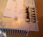
I did a rough layout just for kicks, and it's actually a lot more feasible than I was originally thinking in my head. I've attached an image of what I think the ideal layout would be for 8 channels. You'll have to find a suitable TO-220 mosfet, as well as suitable TO-220 resistors to make it work. the rest is pretty self explanatory, and the BIII would mount just above in the centre, and connect to each channel's input via short wires.
The gate circuitry, along with the output transformers would have to be mounted on a strip of perfboard that connects to each gate (pin bent upwards) and that would be mechanically supported off the heatsink. The voltage busses are easily connected in this arrangement, and the outputs are facing the outside edge for easy access.
Regards,
Owen
Attachments

Beautiful. And that's just using one side of the heatsink. I'd have to tap the holes to fix the devices - but that could be neat too. I didn't realise that the FQA32N20C wasn't a T220 case. I guess the TO3pn case is unnecessarily big for this version... What FET do you have in mind?
And I'm starting to think about FET matching.. How many would I need to buy to get 16 pairs? Not done this before...
As for heat - maybe I should make the PSU have 2 different voltage settings. +-24 (or less) something for standby/uncritical listening and -+40 (or more) for 'winter heating' mode and the best sound.
This is shaping up!
Maravedis
wont having all of the fets and resistors placed so very close to each other on the sink totally ruin its dissipation specs?
nah look go at it, i just dont see performance with an untested fet, already higher thd in 8 channel mode and p2p winding up with such great performance. will probably still sound great though
nah look go at it, i just dont see performance with an untested fet, already higher thd in 8 channel mode and p2p winding up with such great performance. will probably still sound great though
about 50-60 minimum. i did 170 and ended up with about 70 that werent really useable, expect to get lower yield with a smaller number. gm matching is not trivial either. do you have several dmms (only one of which needs to be quite decent) and a signal generator? you also need to take into account die (and thus heatsink and ambient) temperature, as this directly and quite profoundly affects gm
hehe, just picturing what 4 x the above pic plus output caps and supporting components will look like. we demand pics of the finished product.
my skepticism stemmed primarily from 2 things, the massive difference in measured performance between optimized fet choice and random fet choice and a not insignificant measured performance decrease i saw in scope pics between using 2.54mm header and 2mm header on the ackodac multiplied by 10.
something to keep in mind when you push ahead, Dustin, the designer of the sabre dacs, mentioned it was very important to maintain 'line of sight' for the return current paths from the iv stage to the dac.
Last edited:
ahh i see, you were talking about your fets on a heatsink as 'above' (which also only seems to illustrate one side of the dac with devices plus other side on paper). i was talking about what was actually directly above my post ie opc's layout, which is for 4 channels, 2 devices per balanced channel remember and the resistors are on there too.
for 16 channels you of course need 32 fets, 64 power resistors, 32 large value film caps
for 16 channels you of course need 32 fets, 64 power resistors, 32 large value film caps
Last edited:
Qusp - I really am referring to Opc's layout too. It IS for 8 channels. Unless I really have gone totally bonkers. Each fet has 2 power resistors. There are 16 fets on his diagram and 32 resistors = 8 channels. I counted.
Ouch. The price of T220 resistors is crazy! Does anyone know of a cheap source? I might end up gluing 5w w/w to the heatsink. Would wirewounds be a problem in this circuit? Or those Kiwame Carbons might be good...
Maravedis
Ouch. The price of T220 resistors is crazy! Does anyone know of a cheap source? I might end up gluing 5w w/w to the heatsink. Would wirewounds be a problem in this circuit? Or those Kiwame Carbons might be good...
Maravedis
sorry youre right, i was only talking about the circuit, which is only drawn out for one side, the devices are there, but i was only referring to the actual circuit. sorry for the confusion. for some reason i was just thinking the extras were a step and repeat revainder probably. i wasnt thinking of the others there because if i were you i wouldnt pack both sides all in right next to each other when its not necessary (being on either side of the dac), as that will vastly decrease the efficiency of the heatsink.
regarding the resistors, depends on what brand, but they wont come cheap. digikey is probably your best bet, but you will have to put up with a mix of 15w and 30w devices, as last time I checked they didnt have both 200R and 400R in the one rating for caddock. but they also have some ohmite. mouser from memory was the same, only having the 200r in stock. it'll never be cheap though and unless you want to be matching them too, you should definitely stick to 1% parts.
good luck, i'm off to bed. its 6am, thus my slightly acerbic tone, sorry for that, crap but crazy busy night at work on the weekend, well, not on the weekend, but ruining my weekend, gotta do it all over again and supposed to be going out 🙁 i'd be ruined anyway, only had 4hrs last night too. everyone always thinks working for yourself would be so cool.
its not all bad of course, but weeks like this i feel it bad
Last edited:
have you got 2 of those heatsink profiles or just the 1?
I would stay away from wirewounds unless you can find some non inductive ones, which will probably turn out close to the same money. also, i wouldnt skimp on the fets or those resistors, they are basically the only parts in the signal path apart from the caps and no sense going to all this trouble to ruin it with cheap resistors. they'll see quite a bit of heat too, so cheaper ones will be all over the place with their tempco and tolerance.
I would stay away from wirewounds unless you can find some non inductive ones, which will probably turn out close to the same money. also, i wouldnt skimp on the fets or those resistors, they are basically the only parts in the signal path apart from the caps and no sense going to all this trouble to ruin it with cheap resistors. they'll see quite a bit of heat too, so cheaper ones will be all over the place with their tempco and tolerance.
Last edited:
Owen,
LTspice is great. I've pretty much understood the basics already. Thanks for encouraging me to take the plunge!
I'm off on an internet-free holiday now, but really looking forward to getting further with this in a couple of weeks time.
Maravedis
LTspice is great. I've pretty much understood the basics already. Thanks for encouraging me to take the plunge!
I'm off on an internet-free holiday now, but really looking forward to getting further with this in a couple of weeks time.
Maravedis
Hi Maravedis,
I'm glad you gave it a shot; it really is a lot more straightforward than people seem to think, and it's a great way of trying (and learning about) pretty much any circuit you can dream up. The only tricky part is modifying the library to include different parts you find model for.
I'm looking forward to seeing your progress on this, so keep us all posted on what you end up doing.
Enjoy your vacation!
Cheers,
Owen
- Home
- Source & Line
- Digital Line Level
- A New Take on the Classic Pass Labs D1 with an ESS Dac