Hi have been toying with this idea for a while, and since have joined this forum have decided to publicize ideas , ( actually dont have that long to live so ideas bloody useless to me )
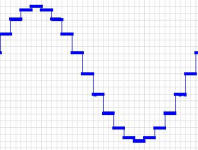
Ideal output of a DAC ( no filtering, over sampling etc ), first attachment
The problem being ( in the frequency domain ) the "spaces" between the samples. And the transition between one bit and the next ( the rise time ) . Both of these create high frequency "images" in the frequency domain. Its this problem that causes the responses of filtering, oversampling etc etc etc.
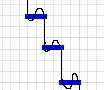
How about we replace the "spaces" with a fixed frequency sine wave , second attachment.
Am i correct that if the superimposed sine wave is pure, we suddenly have a very narrow band noise ? Instead of a bloody wide band noise ?
And that suddenly filtering becomes easy ???
Ideal output of a DAC ( no filtering, over sampling etc ), first attachment
The problem being ( in the frequency domain ) the "spaces" between the samples. And the transition between one bit and the next ( the rise time ) . Both of these create high frequency "images" in the frequency domain. Its this problem that causes the responses of filtering, oversampling etc etc etc.
How about we replace the "spaces" with a fixed frequency sine wave , second attachment.
Am i correct that if the superimposed sine wave is pure, we suddenly have a very narrow band noise ? Instead of a bloody wide band noise ?
And that suddenly filtering becomes easy ???
Attachments
I am sure someone more digital world savvy with jump in on this but technically speaking I think that's what dither is all about - adding in random high frequency noise to smooth out the steps between the samples, then filtering out the noise after the reconstruction of the analogue waveform has taken place.
You still have the sharp steps. All you have done is replace the flat top. Anyway, where are you going to get the smooth sine wave from? The DAC can't do it as it is clocking at the much slower rate of the edges.
This idea won't work. You need to gain more understanding of sampling, reconstruction etc.
This idea won't work. You need to gain more understanding of sampling, reconstruction etc.
Am i correct that if the superimposed sine wave is pure, we suddenly have a very narrow band noise ?
Seems you've superimposed the DAC's output on a sinewave rather than as it was formerly, superimposed on nothing at all. I can't see that as a step forward myself, substituting a narrow band noise for no noise at all.
You still have the sharp steps. All you have done is replace the flat top. Anyway, where are you going to get the smooth sine wave from? The DAC can't do it as it is clocking at the much slower rate of the edges.
This idea won't work. You need to gain more understanding of sampling, reconstruction etc.
The drawing is not so good, but the rise times between the steps should also be part of the sine wave , thus the "edges" will have a sine-wave roll off, removing , i think , the "images" created in the frequency domain by that transition
The sine wave itself can come from a separate "pure" oscillator, it can be introduced by custom front-end for the dac, one can easily reuse the system clock which in most cases is operating at 10x or more the sampling rate, and in most cases is a low harmonic "pure" sine wave before it is turned into square by a latch or comparitor or such. not trivial circuit shape ( to get it right ) but defiantly realizable , the only reason have not produced a working circuit is cos just cannot be bothered, i got my own problems at the moment 🙂
The question is "IF" the electronics are realized , would the resultant filters needed be better or worse than what is currently used? It is my understanding that if for example if i were to use a 1mhz sine , i would only have to filter EXACTLY 1 mhz, ( a notch filter for example ) , i could ignore everything else ??
BUT as you pointed out i am a little green in this area, thats why need more expert opinion 🙂
Seems you've superimposed the DAC's output on a sinewave rather than as it was formerly, superimposed on nothing at all. I can't see that as a step forward myself, substituting a narrow band noise for no noise at all.
Well hopefully i have removed the "edges" between transitions, thus a lot of crap in the frequency domain is gone ?????.
In the real waveform there is LOTS going on in the space between samples, anything we try to put between those transitions is just a guess, and is not that the basic problem with digital reproduction ??
As someone mentioned its like dithering , but in that case we are randomly placing small values in the gaps, thus preventing LSB "sticking" and enriching the sound ( as is done very successfully in digital pictures to enhance the content for human eyes ).
But that produces "white noise" which cannot be filtered, does this solution ( if it is even a solution ) have the advantage of doing the same , if not better, and still allowing one to very easily filter the "noise" out ???
The first photo is really what you should be aiming to achieve, in particular at 20kHz. The least ringing, overshoot, the fastest rise times are all desirable and will approach theoretical limit of a DAC, if it is loaded appropriately. You have probably guessed already that only R2R DAC's could possibly give you such response, and in addition -> only a true NOS topology can get you there. The sine wave, as pointed out by others, will have to be superimposed (generated) "by meanings other than a DAC" - DAC can conduct at a specific clock interval - and at that time -> it will give a specific output (current) value.
Well hopefully i have removed the "edges" between transitions, thus a lot of crap in the frequency domain is gone ?????.
Not from the drawing - those vertical lines between the stair treads do look rather vertical. Perhaps you were envisaging something along the lines of Hawksford's raised-cosine DAC idea (his AES paper, Nov 1994)?
In the real waveform there is LOTS going on in the space between samples, anything we try to put between those transitions is just a guess, and is not that the basic problem with digital reproduction ??
In my understanding there's no guessing going on as what's between the impulses is precisely constrained by the bandlimiting at the input. There's always only going to be one way to join up the dots within the band limit constraint.
paralleling dac
Yes is best way this is possible by paralleling some number of dac...like the tda1543
schematic 🙂
I am sure someone more digital world savvy with jump in on this but technically speaking I think that's what dither is all about - adding in random high frequency noise to smooth out the steps between the samples, then filtering out the noise after the reconstruction of the analogue waveform has taken place.
Yes is best way this is possible by paralleling some number of dac...like the tda1543
schematic 🙂
Not from the drawing - those vertical lines between the stair treads do look rather vertical. Perhaps you were envisaging something along the lines of Hawksford's raised-cosine DAC idea (his AES paper, Nov 1994)?
In my understanding there's no guessing going on as what's between the impulses is precisely constrained by the bandlimiting at the input. There's always only going to be one way to join up the dots within the band limit constraint.
Like said drawing not very good, will have to do it better i see 🙂. The Idea is to join all the dots with pure a sine wave ( or whatever fill-in is appropriate, the one with the least harmonics ) so square wave steps no longer exist.
will have a look at that paper, thank you very much.
Well there is defiantly guessing going on, if one were to up the sampling rate by x10 , then one would suddenly have a lot more information to fill in the gaps. Likewise if you compare the original waveform with the sampled one they look different yes ?
If one could "draw" onto an oscilloscope, one could fill in the gaps by hand , and in the case of a simple sine wave would that not be far superior to the series of digital and analog filters used which in effect are trying to do exactly the same thing ???
There are some drawings relating to the DAC I mentioned shown on page17 of this document - http://citeseerx.ist.psu.edu/viewdoc/download?rep=rep1&type=pdf&doi=10.1.1.211.4600
If you compare input waveform to the 'staircase' waveform they look different yes, but the staircase isn't the output waveform, it needs anti-imaging filtering. Upping the sample rate by a factor of 10 wouldn't give different results for the intervening samples assuming the input bandlimiting was identical.
I can't think how drawing by hand would come close to the mathematical precision of an anti-imaging filter.
The first photo is really what you should be aiming to achieve, in particular at 20kHz. The least ringing, overshoot, the fastest rise times are all desirable and will approach theoretical limit of a DAC, if it is loaded appropriately. You have probably guessed already that only R2R DAC's could possibly give you such response, and in addition -> only a true NOS topology can get you there. The sine wave, as pointed out by others, will have to be superimposed (generated) "by meanings other than a DAC" - DAC can conduct at a specific clock interval - and at that time -> it will give a specific output (current) value.
????? HUH , now am really confused, you say the first trace is desirable???
I thought the general idea was to make the analog input and digital output look the same on an oscilloscope ( that being a fair approximation as to whats going on in the freq domain ), sorry mate but the first trace dont look anything like a smooth sine wave that comes from a wein-bridge oscillator.
Yea i am a design engineer, im not really afraid of creating a specific front end to implement it, some zero-crossing going on, and a modulated low noise source follower, not rocket science. Or it could be incorporated into a discrete r2r VERY easy. There would be a few timing issues, and obviously a shed load of hidden problems one would stumble over buit nothing thats a show stopper.
There are some drawings relating to the DAC I mentioned shown on page17 of this document - http://citeseerx.ist.psu.edu/viewdoc/download?rep=rep1&type=pdf&doi=10.1.1.211.4600
If you compare input waveform to the 'staircase' waveform they look different yes, but the staircase isn't the output waveform, it needs anti-imaging filtering. Upping the sample rate by a factor of 10 wouldn't give different results for the intervening samples assuming the input bandlimiting was identical.
I can't think how drawing by hand would come close to the mathematical precision of an anti-imaging filter.
Good article !!!! Will give it a very good read tonight
Ok get you, but in my idea would i only need 1 very simple notch filter ?? ( to remove the fundamental sine ) thus making the filtering so much more accurate ???
Band limiting the input ? In audio terms does that not mean a shed load more filters before the analog waveform hits the ADC ??
As far as i am aware, ANY filter colors the sound, it does not matter where the poles or zero's are, you WILL be able to tell the difference ( maybe not audible, but that a different subject ) if the filter is in line.
I was under the impression what we are after is a system with as FEW filters as possible.
Finally i have a lot ( ok just 3 🙂 but i have very few mates ) of engineer mates who would not trust a digital filter in a clock radio let alone hi-fi sound , they say that current digital filter technology is S*** , they claim the current crop of digital filters ( and indeed DS dacs ) all come from RF ( cellphone) technology and thoroughly unstable for high end audio.
Last edited:
I can't so far see how your sine proposal adds anything (other than a sinewave) - the steps are going to be there unless all the time between samples is taken up with gentle slewing in which case you will have removed some of the ultrasonics, but taken much of the signal away with it too.
Bandlimiting the input by means of some filter isn't optional before the signal gets to the ADC, its mandatory.
Filters affect the sound yes but not having a filter affects the sound too - I've found that fairly steep bandlimiting after the DAC improves a NOS implementation, subjectively and objectively (in reducing the images). No need to have a digital filter, an analog AIF does the job well enough.
That's not the ideal output. That's the cheapest kind of interpolation known as zero-order hold.Ideal output of a DAC ( no filtering, over sampling etc ), first attachment
Here's what that gets you (1 Hz sampling rate):
An externally hosted image should be here but it was not working when we last tested it.
Droop and not very good suppression of images.
There are no "spaces". You sample at TThe problem being ( in the frequency domain ) the "spaces" between the samples.
Given a bandlimited input signal there is theoretically no loss, because we can add the redundant dots "in between" back in using interpolation.
Reconstruction is no matter of "connecting the dots". Neither with vertical lines (zero-order hold) or with straight lines (linear interp. or first-order hold).
This should make that clear and show you why there's droop in the passband:

Given an appropriate reconstruction filter you will get back the blue sine wave from the green samples.
That's right but it's by design.And the transition between one bit and the next ( the rise time ) . Both of these create high frequency "images" in the frequency domain. Its this problem that causes the responses of filtering, oversampling etc etc etc.
Again, the filtering theoretically doesn't change anything, it just reconstructs the original input (that was bandlimited).
How about we replace the "spaces" with a fixed frequency sine wave , second attachment.
Am i correct that if the superimposed sine wave is pure, we suddenly have a very narrow band noise ? Instead of a bloody wide band noise ?
And that suddenly filtering becomes easy ???
No, but you've added more "noise".
idea for dither
how do you think about generating a 1 bit digital noise and add it to the I2S signal (sample
part) to crate dither ...?!?😕
New samples are up sampled
I am sure someone more digital world savvy with jump in on this but technically speaking I think that's what dither is all about - adding in random high frequency noise to smooth out the steps between the samples, then filtering out the noise after the reconstruction of the analogue waveform has taken place.
how do you think about generating a 1 bit digital noise and add it to the I2S signal (sample
part) to crate dither ...?!?😕
New samples are up sampled
Last edited:
No. As I said, you need to learn some more.vecna said:It is my understanding that if for example if i were to use a 1mhz sine , i would only have to filter EXACTLY 1 mhz, ( a notch filter for example ) , i could ignore everything else ??
Newbies often come up with 'solutions' to 'problems' they perceive with digital audio. Two snags:
1. the 'problem' often isn't a problem, or has a known solution
2. the 'solution' isn't a solution, and in addition adds new problems
I used to do it myself, until I learnt enough about sampling and reconstruction to realise that the industry has already solved all the problems which need solving. In many cases the issue is that there is insufficient understanding of the roles of the anti-aliasing filter and the reconstruction filter.
Hi, I'm one Newbie here too, learning on this forum.
- If industry has already solved all the problems with 16/44, why they develop 24/96, 24/192 and DSD?
- If anti-aliasing filters and the reconstruction filters working perfect, how can 1kHz sine wave signals looking bad like in pics in Stereophile measurements tests?
Just questions, I don't know the answers.
Last edited:
Solved 16/44 ?
Do you think the CD reproduction is at the best of system ? i have hear a type of nos and
i think many others steps is needed on digital CD 🙂
Hi, I'm one Newbie here too, learning on this forum.
- If industry has already solved all the problems with 16/44, why they develop 24/96, 24/192 and DSD?
- If anti-aliasing filters and the reconstruction filters working perfect, how can 1kHz sine wave signals looking bad like in pics in Stereophile measurements tests?
Just questions, I don't know the answers.
Do you think the CD reproduction is at the best of system ? i have hear a type of nos and
i think many others steps is needed on digital CD 🙂
- Status
- Not open for further replies.
- Home
- Source & Line
- Digital Source
- A new DAC idea