
hi tarasque
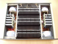
clever design with inside heatsink and outside amp and supply
but i hope there is a free big hole underside for airflow
and maybe big stand off foot for airflow would be a good thing
tell me more about your power supply transfo + cap
bye I m sure you will be happy with A30 like me with A3
clever design with inside heatsink and outside amp and supply
but i hope there is a free big hole underside for airflow
and maybe big stand off foot for airflow would be a good thing
tell me more about your power supply transfo + cap
bye I m sure you will be happy with A30 like me with A3
Member
Joined 2002
Nice Design Concept. Looks really impressive. I like the wood side panels. Normaly i'm not a fan of wood on any audio ( component's ) but that added a really nice touch.
Good job..
Jase
Good job..
Jase
I'm using parallel windings of 22-0-22V (bigger xformers would not fit in the space I had left on either side of the heatsink.
The caps are 6800/50V Nippons, 24 pieces per channel.
Yes, you are right...There is a tunnel under the heatsinks for the airflow and sufficiently high feet.
The design was actually dicted by the parts I had in my shop. I was determined not to buy expensive parts like xformers, heatsinks and power caps. So I fiddled around with the existing parts and finally came up with this design.
Congratulation Tarasque, very nice job!
Did you measure the heat-sinks temp?
A30 is a lovely amp, I still dont believe my ears...
Did you measure the heat-sinks temp?
A30 is a lovely amp, I still dont believe my ears...
Heatsink temperature is 23C above ambient temp.
I have tweeked the power supply voltage to the maximum @ a delta T of 23C with the resistors between the caps.
My power supply is 33V and the Iq is 0,83A per fet.
I have tweeked the power supply voltage to the maximum @ a delta T of 23C with the resistors between the caps.
My power supply is 33V and the Iq is 0,83A per fet.
That is a superb figure indeed!!Heatsink temperature is 23C above ambient temp.
Steen😎
I like to build this amp too, do you have the circuit diagram. can you send it to me. too bad that I do not have a lot of time, I guess I will take half year to finish it if I start building it.
HI Tarasque
Great job it is a very nice amp , nice design.
How do you like the sound , did you com pared with other amps .
I have the same PC boards from P Daniel . I'm in the process to put it together . May be next week .
Already finished with the stuffing just I have to ad the driver mosfets , 10pF and 1nF capacitors .
I would like to ask for some help . Would you please let me know if you use any resistor for R8 or jumper ?
I don't know if I have to use resistor or jumper . I afraid to hook up the power with out being sure .
Please let me know .
Regards
hc167 said:I like to build this amp too, do you have the circuit diagram. can you send it to me. too bad that I do not have a lot of time, I guess I will take half year to finish it if I start building it.
Don't feel bad! My first one took the better part of a year🙂
Go for it.
Originally posted by hc167 :
I like to build this amp too, do you have the circuit diagram. can you send it to me. too bad that I do not have a lot of time, I guess I will take half year to finish it if I start building it.
Originally posted bympmarino:
Don't feel bad! My first one took the better part of a year
Go for it.
Dont worry about the time it takes to build an amp...
It took me the better part of two years to plan and design all the aspects of this amp.
Building it then took another 7-8 month.
Currently in the project stage are:
P1.7 (neerly completed)
onno (neerly completed)
X2
X350
Already build: Mini-Aleph:
Passdiy miniAleph
Tarasque:
good to know that you have make so many pass diy amp. The problem I have is build my own chassis. I am thinking of getting one from www.hifi200.it. But I do not know how I am going to drill all those holes. Your chassis look very nice. Once I solve the problem of chassis, I think I can finish it quickly. Unless I do not want to build professionally. otherwise, all the minor thing, like holding the pcb on the chassis, I need to think about it carefully. but thanks a lot for your input.
good to know that you have make so many pass diy amp. The problem I have is build my own chassis. I am thinking of getting one from www.hifi200.it. But I do not know how I am going to drill all those holes. Your chassis look very nice. Once I solve the problem of chassis, I think I can finish it quickly. Unless I do not want to build professionally. otherwise, all the minor thing, like holding the pcb on the chassis, I need to think about it carefully. but thanks a lot for your input.
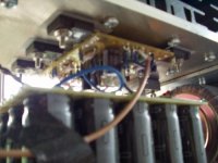
That is indeed a nice compact design. But I cringe at seeing what appears to be the input wire running so close to a power transformer: Have you tried routing it differently to see if the sound improves?
Hi Tosh
Before I ran the wire that way, I did tests looking at the output of the amp for hum.
I did not see a difference between the wires near the xformer and ran far from them.
Before I ran the wire that way, I did tests looking at the output of the amp for hum.
I did not see a difference between the wires near the xformer and ran far from them.
gaborbela said:HI Tarasque
Great job it is a very nice amp , nice design.
How do you like the sound , did you com pared with other amps .
I have the same PC boards from P Daniel . I'm in the process to put it together . May be next week .
Already finished with the stuffing just I have to ad the driver mosfets , 10pF and 1nF capacitors .
I would like to ask for some help . Would you please let me know if you use any resistor for R8 or jumper ?
I don't know if I have to use resistor or jumper . I afraid to hook up the power with out being sure .
Please let me know .
Regards
I finally had the time to do some serious listening. I could use Teake's P1.7 as pre-amp and used my Seas Thor's.
If compared to the mini-A's the sound is more complete and less "loud"
The mids are truely wonderfull and the soprano from "La traviata" has no coloration at all.
The most striking thing is way the musical picture is drawn...in rich full strokes, without the least signs of doubt. The increadable dynamics is the biggest step forward.
I used the ground resistors (5,6 ohm) at the input to minimize the effect of a ground loop.
To come back at the power supply: I used the CRC optoin after simulations in Pspice. At 50Hz, the complex component of the coils are less or equal to the resistive part.
Also using as little as 0,4 Ohm will give you about 70mV ripple if you use 2 banks of about 30mF.
Positioning the amplifier PCB close to the high current wires will give more noise than the power supply ripple.
I hope this helps.
Next project will be to setup the SME 30 turn table with the ono. I'm hoping for more definition from vinyl that from the CD......
- Status
- Not open for further replies.
- Home
- Amplifiers
- Pass Labs
- A new A30 has started to sing!