Hello to everyone, I am a new member here and I was advised by another member to start a build thread and watch the advice and tips come flowing my way.
In the way of background, I am new to DIY, having only built a cheap CMOY headphone amp and a SOHA tube hybrid headphone amp based on the writeup at www.mb3k.com. I am currently a 4th year undergraduate studying physics, so I have some background but nothing compared to the level of knowledge of everyone here.
My current setup is as follows:
Sources:
Yamaha YP-B4 Turntable
Rega Planet CDP
Apple Airtunes
Preamp:
NAD 7000 Moniter
Amps:
SOHA
B&K ST-140
Speakers:
Wharfedale Diamond 9.2
Sennheiser HD580
I am thinking of upgrading my TT, and also now wanting very badly to build a preamp with some tubes in it (after my WOW! experience with the SOHA). I know my system is nothing to drool over, but it is very adequate for my listening enjoyment.
Onto the quest:
I want to build a 12B4. Since I am a college student without a steady income, I need to keep the costs down, which I was assured was possible in another thread I started.I have read through a lot of a thread started by Mark A. Gulbrandsen called "Yet another 12B4 line stage, or is the 12B4 better than the Grounded Grid." After my reading I emerged more confused.
I am uncertain about a couple of things to start with, namely the favored schematic. I read that Brian Beck's is a definite upgrade over the original, but that there were some electrolytic caps that needed to be bypassed by decent filmcaps for a preamp application. Along with the schematic comes the need for a PS schematic. Since I am new at all this, I am not really sure how to make a schematic out of all the instructions people give, so I am wondering if there are schematics out there for what I am looking for.
One option for PS that I am considering is this one: http://www.glass-ware.com/tubecircuits/High_Voltage_Regulator.html. It seems that the parts required are inexpensive and it is relatively easy to construct. I am somewhat confused about where I would connect a transformer to the regulator, and also what sort of transformer I would need for this.
Since this is a build thread, I will update irregularly as I work on this or as questions arise, including posting BOM's for approval and pictures as necessary.
I appreciate any and all advice and look forward to working on this line stage!
Best,
Colin
Hi, I would suggest you use 2 x VR150 voltage regulator tubes to give you 300V. I'm not sure how expensive those are in your area, but they're cheap here where I am. They also give you a nice purple glow, and that's a conversation piece. This is very simple to implement compared to that circuit you posted.
I'd use SS rectifiers and a couple of 450V (CRCRC) capacitors before the VR150, to keep costs down.
I can make you a schematic for this.
We will need to know how you'd be operating you 12B4, so that we can determine the current requirements for the PSU.
If you're leaning towards Brian's LM317 CCS cathode configuration, you can use decent Illinois film capacitors to bypass the electrolytic. Illinois caps are not that expensive.
ps.
Here's the Illinois Cap MPW series (Polypropylene)
Illinois Capacitor give samples, so this will come in handy.
I'd use SS rectifiers and a couple of 450V (CRCRC) capacitors before the VR150, to keep costs down.
I can make you a schematic for this.
We will need to know how you'd be operating you 12B4, so that we can determine the current requirements for the PSU.
If you're leaning towards Brian's LM317 CCS cathode configuration, you can use decent Illinois film capacitors to bypass the electrolytic. Illinois caps are not that expensive.
ps.
Here's the Illinois Cap MPW series (Polypropylene)
An externally hosted image should be here but it was not working when we last tested it.
Illinois Capacitor give samples, so this will come in handy.
arnoldc said:Hi, I would suggest you use 2 x VR150 voltage regulator tubes to give you 300V. I'm not sure how expensive those are in your area, but they're cheap here where I am. They also give you a nice purple glow, and that's a conversation piece. This is very simple to implement compared to that circuit you posted.
I'd use SS rectifiers and a couple of 450V (CRCRC) capacitors before the VR150, to keep costs down.
I can make you a schematic for this.
We will need to know how you'd be operating you 12B4, so that we can determine the current requirements for the PSU.
If you're leaning towards Brian's LM317 CCS cathode configuration, you can use decent Illinois film capacitors to bypass the electrolytic. Illinois caps are not that expensive.
ps.
Here's the Illinois Cap MPW series (Polypropylene)
An externally hosted image should be here but it was not working when we last tested it.
Thanks for the reply. I would love to see a schematic since I don't really understand the operation of these tubes. Also, I have seen the notation CRCRC before, but I am not 100% clear on what this refers to. I have dealt with RLC circuits in my analysis course, so I am assuming it is a network of caps and resistors of some sort, but it would be great to learn more about what these different configurations refer to.
I am not sure exactly what you mean by how I will be operating the unit, but I will give it a shot. I basically want to replace my NAD 7000 with the 12B4 unit. I want to have at least 4 or 5 inputs, and at least two outputs. I will need to send the pre to the power amp and be able to control the volume just like my NAD. I am hoping to build a phono stage after building this project successfully to incorporate my turntable into the setup. I am not sure exactly what you mean by this, so if I didn't properly answer the question let me know and I will clarify as best as I can.
Also, when you say bypass the electrolytics does that mean to just altogether leave them out and use a film cap in their place? What is the purpose of this?
Best,
Colin
planet10,
Thanks for the schematic (the first one). It raises a couple of questions for me:
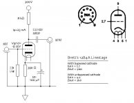
1. There is one unlabeled resistor and one unlabeled capacitor, what the required values for these components?
2. I assume I am getting ahead of myself here, but what is the pin configuration of the 12B4? How does that correspond to this diagram?
3. I am assuming that the open/closed circles on the right and left upper corners are refering to inputs/outputs, if so, which is which?
Thanks!
Colin
Thanks for the schematic (the first one). It raises a couple of questions for me:
1. There is one unlabeled resistor and one unlabeled capacitor, what the required values for these components?
2. I assume I am getting ahead of myself here, but what is the pin configuration of the 12B4? How does that correspond to this diagram?
3. I am assuming that the open/closed circles on the right and left upper corners are refering to inputs/outputs, if so, which is which?
Thanks!
Colin
The second is very much clearer to me, but I still have a couple of questions now. A previous poster mentioned using two VR150s to acheive 300V while giving a cool purple glow effect (which is very appealing to me 🙂 ). I notice that Brian's schematic requires 320V in, so is there a way that I could create 320V using these neat purple-glowing-tubes while keeping the cost at a minimum? Or am I already getting too far ahead of myself and should I just get back to a more simple SS power supply for my first try?
Also, when you say bypass the electrolytics does that mean to just altogether leave them out and use a film cap in their place? What is the purpose of this?
Bypassing the elecrolytics does not mean to leave them out, it means to place a small valued film cap in parallel. Higher value caps tend not to work as well at higher frequencies so the lower value film caps are used to improve performance.
A small value bypass cap across a 220uF power supply cap will help to eliminate high frequency noise from the rectifier or wall supply. Similarly there can be high frequency noise generated by a CCS which can be eliminated with a bypass cap.
Generally a cap a couple of orders of magnitude less than the initial capacitance can be used, probably a 1uF film cap would be appropriate for 100uF or 220uF electrolytics.
Some diy'ers swear by multiple bypass caps, i.e. 100uF bypassed by 1uF bypassed by 10nF for example. Never tried it to that degree myself though.
thereverend said:So Arnold, how would I go about implementing that VR150 into Brett's power supply?
Hi Colin, I changed my mind about recommending it to you because the VR150 will only give you 40mA... Sorry.
Yup, start with Brett's version. You can't go wrong.
I just want to remind you that if you're using the phonostage of your NAD, you need to route it to the 12B4 (is there a tape out?) i.e.,
Yamaha 'table -> phono stage -> 12B4 preamp -> power amp
vs.
CD player -> 12B4 preamp -> power amp
I just want to remind you that if you're using the phonostage of your NAD, you need to route it to the 12B4 (is there a tape out?) i.e.,
Yamaha 'table -> phono stage -> 12B4 preamp -> power amp
vs.
CD player -> 12B4 preamp -> power amp
arnoldc said:Yup, start with Brett's version. You can't go wrong.
I just want to remind you that if you're using the phonostage of your NAD, you need to route it to the 12B4 (is there a tape out?) i.e.,
Yamaha 'table -> phono stage -> 12B4 preamp -> power amp
vs.
CD player -> 12B4 preamp -> power amp
Yes, like that. Well, like this, 3 routes for now:
CDP -> 12B4 > Amp
TT > NAD > (From tape out) > 12B4 > Amp
Airtunes > 12B4 > Amp
I also want my 12B4 to have a tape out for my headphone amp and one extra tape out just for anything else that comes along. Eventually I want to build a nice phonostage too, but since it is critical that it is done very carefully I thought this was a good place to start.
Does anyone have any recommendations where I should start sourcing some of these harder to find parts? I looked up the Auricap 3.3uF @ 450V and found that they are very expensive @ $20/per over at www.tubedepot.com. Any better places to look where I will find almost everything in one place in order to minimize shipping costs? Thanks!
EDIT: Also, what are the recommended brands for parts? Are Vishay/Dale good for the resistors, and should I be looking at a specific type of resistor?
EDIT: Also, what are the recommended brands for parts? Are Vishay/Dale good for the resistors, and should I be looking at a specific type of resistor?
How about Illinois Cap or Electrocube... Are they available there? How much are Riken, Kiwame, Allen Badley, or Mills over there?
Try also looking at PartsConnexion.com or Angela.com or Antique Electronic Store (AES)
Try also looking at PartsConnexion.com or Angela.com or Antique Electronic Store (AES)
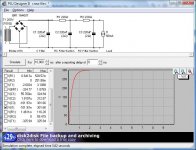
I suggest that you look up the Duncan Amps web page. Download the PSUD program (it's the one Arnoldc used for the power supply schematic). It's free, easy to use, and an excellent introduction to circuit simulation tools. On the Duncan Amp pages, you will also find a link to the TDSL, or Tube Data Sheet Locator. There you will find the data sheets for all the common tubes and many uncommon ones too.
Regarding components, I wouldn't worry about it at this point, as you are operating on a limited budget. Get a decent power supply transformer (not undersized) - it won't be expensive. If you have an electronics surplus store in your area, you can probably find the capacitors and resistors you need. Do a good job on the chassis layout and leave plenty of room and organize your parts neatly. That way, it's easy to play with upgraded components at any future time, including subustituting the current source for the cathode resistor.
Sheldon
- Status
- Not open for further replies.
- Home
- Amplifiers
- Tubes / Valves
- A Neophyte's 12B4 Build Thread