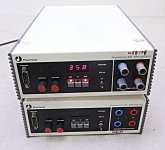
After the recent Bio-Rad 500/200 HV electrophoresis supply thread, I picked up a Pharmacia LKB EPS 500/400 supply and a Hoefer PS500XT supply, both switching type electrophoresis supplies, and cheap ($64 and $105 off Ebay).
I mainly was just interested in how well these things might work for tube Amp. design work. These are rated for up to 200 Watts, 0-500V and 0-400 mA, and are regulated and metered. These are typically readily available, at cheaper prices than say a Heathkit SP-17 ( 40 Watts, 400V, 100 mA). I figure some other DIY's might be interested in what I found.
Here are some measurements.
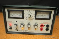
Pharmacia LKB EPS 500/400 unit:
Requires less than 1 mA load to activate (ie, has a no load safety shut-down).
Also has a leakage indicator and shut-down. (a ground fault interrupter safety, detects stray current going to ground, like used in modern kitchen outlets, super safe)
500V, 400 mA, 200 Watt max specs.
Weight 9 Lbs.
Dimensions: 3.75" H x 8.625" W x 16" D (including heatsink and knobs)
(Height not including rubber feet on bottom, another .25") Uses up bench space, but one could stack multiple units.
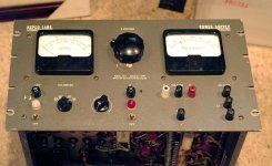
Power switch on the back is very hard to switch. Does have an easy standby switch on the front panel. V and I knobs are small and un-comfortable to use.
Only one digital readout meter, button switchable between actual Vout, actual Iout, V knob setting, and I knob setting. (the extra knob setting readouts are nice, but it definitely needs an extra Vout meter operating 100% of the time)
Has current limiting, with LED V and I mode indicators. Current limiting just turns off the converter, somewhat slow for the Vout to decay.
Euro style deep recessed mini banana plug output terminals (electrophoresis style)
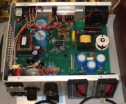
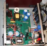
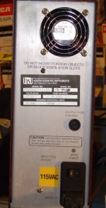
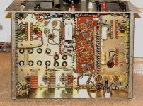
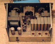
Operates at 28.5 KHz using a flyback converter design using Philips TDA1060 controller chip with a heatsinked TO-5 driver transistor. Single switching transistor, TO-3, (probably bipolar) Heatsinked on the back, no fan. Two resistors on PC board getting rather hot (board browned around the 3 Watter)
Electrical OUTPUT NOISE:
20 Vp-p 60Hz (full load, 500Vout)
4 Vp-p HF switching noise (full load, 28.5 KHz)
Common mode noise: 8 Vp-p CM at 120 Hz, 1 Vp-p CM at HF (28.5 KHz)
Has no line input line filter (60 Hz 120VAC) except two small AC caps to ground. Just rectifiers into 2 x 680 uF DC Caps
Has no output HF filter except 4 x 22uF DC Caps in series.
POWER CONSUMPTION: 11 Watts no load, 33 Watts with 15W load, 218 Watts with 187.3 Watt load (delta = 30.7 Watts loss)
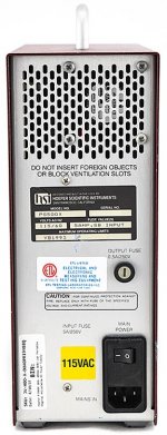
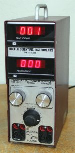
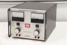
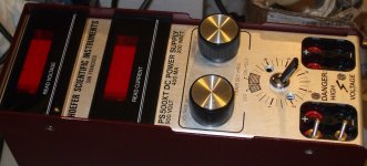
Hoefer PS500XT unit:
No safety features. ( just recessed standard banana plug electrophoresis jacks)
500V, 400 mA, 200 Watt max. specs
Weight 6 Lbs. Has easy carry handle on top.
Dimensions: 10.75" H (+ 1.25" for handle and rubber feet), 4.125" W x 10.125" D (including knobs) Minimal bench space used, nice. Easy portable.
Power switch on back, and also on the front (rocker for PS500X, timer knob for PS500XT) No easy standby switch. The 500XT timer knob version does NOT have a definite OFF detent!! Even rotates around past the off position to ON again! (dangerous!!) V and I knobs are big, comfortable to use.
Two LED digital meters, actual Vout up top, and actual Iout below that)
The I knob sets current limiting, but there is NO LED indicator when running in current limit mode. (annoying) And the current limiting just turns off the converter, it takes 10 seconds!! for the Vout to decay without additional loading.
Recessed standard banana jacks for output.
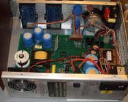
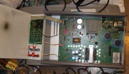
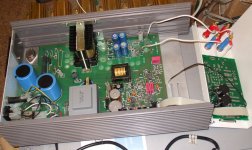
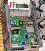
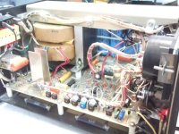
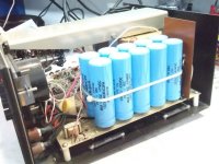
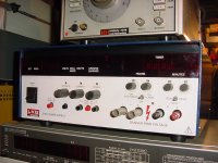
Operates at 74 KHz half bridge converter (effectively 148 KHZ charge pulses) using 4 IRF830 Mosfets (parallel'd pairs) and using a TL594CN controller chip with an added dual gate driver chip. Has two 20 Watt!! snubber resistors that run HOT. These are off the PC board enough to avoid a brown board. Early units had no fan, just perforated vents on back. Some of these early units can be seen with a fan added as a mod, on Ebay!!! Later units have a round 12 VDC fan on back designed in. And noisy as Hell. (I modded the unit here to run with just 6 VDC for the fan, and it is now quiet and stays cool enough.)
Electrical OUTPUT NOISE:
250 mVp-p 120 Hz noise (400 mA load)
125 mVp-p HF 143 KHz noise (400 mA load)
Common mode noise: 4 Vp-p 120 Hz, 2 to 2.7 Vp-p (load) HF 143 KHz noise.
Has no line input filter (120 VAC, 60 Hz) except two small AC caps to ground. Just rectifiers into 2x 680 uF DC Caps.
Has no output HF filter except 3x 220uF 200VDC Caps in series.
POWER CONSUMPTION: 12.5 Watt NO load with a High Vout setting, 6.25 Watts no load at 0 Vout setting, 214 Watts with 166 Watt load (delta = 48 Watt loss)
SUMMARY:
The Pharmacia/LKB unit needs a 2nd digital Vout meter, that is always indicating. There is room on the front panel for that addition if the two extra output terminals are eliminated. The unit runs quiet, could be used as a stationary power supply for a tube amplifier, IF the Electrical NOISE problems are fixed.
The Hoefer unit needs added LED V and I mode indicators (at least an I mode LED) added. No provision for obtaining this signal from the controller chip unfortunately. May be able to tap off a crude I mode indicator from the LM358P OP Amp measuring the output current for the controller. (unit does current limit according to the I knob setting, you just can't visually tell when)
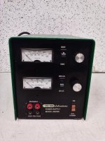
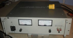
The easy V and I knob controls are well suited for bench top use. But needs an easy standby switch added for safety. The fan quieting mod is essential!! I changed the stupid timer/knob to a toggle switch with a BIG insulated toggle handle. (no more need to read the manual to figure out how to turn it off in an emergency!!) Note the DIY added fan in the 4th pic (old style Hoefer).
Both units need added line input filtering AND HF output filtering. ESPECIALLY the Pharmacia LKB unit!! Common mode HF output filtering too. Most bench switching supplies use a full C - L - C - CM choke filter on the output. I've noticed that Xantrex XHR supplies also have a shunt Mosfet across the output to pull the Vout down quickly (1 mSec) when either the Current Limit or Over Voltage modes activate. This -could- be added to these units IF an I limit signal is available. Especially useful after adding more filter Caps, since those will further delay the output voltage decay. Might save some tubes from melting down occasionally.
These switching type supplies generally are not recommended for screen grid supplies. (could use your old Heathkit SP-17, or even better, a Xantrex XT-250 linear supply with I limiting, or the Bio-Rad 500/200 or a Hoefer Scientific PS500 linear unit) Because switching types are usually slow responding to over current limiting, and a linear regulated supply is fast responding.
..
I mainly was just interested in how well these things might work for tube Amp. design work. These are rated for up to 200 Watts, 0-500V and 0-400 mA, and are regulated and metered. These are typically readily available, at cheaper prices than say a Heathkit SP-17 ( 40 Watts, 400V, 100 mA). I figure some other DIY's might be interested in what I found.
Here are some measurements.
Pharmacia LKB EPS 500/400 unit:
Requires less than 1 mA load to activate (ie, has a no load safety shut-down).
Also has a leakage indicator and shut-down. (a ground fault interrupter safety, detects stray current going to ground, like used in modern kitchen outlets, super safe)
500V, 400 mA, 200 Watt max specs.
Weight 9 Lbs.
Dimensions: 3.75" H x 8.625" W x 16" D (including heatsink and knobs)
(Height not including rubber feet on bottom, another .25") Uses up bench space, but one could stack multiple units.
Power switch on the back is very hard to switch. Does have an easy standby switch on the front panel. V and I knobs are small and un-comfortable to use.
Only one digital readout meter, button switchable between actual Vout, actual Iout, V knob setting, and I knob setting. (the extra knob setting readouts are nice, but it definitely needs an extra Vout meter operating 100% of the time)
Has current limiting, with LED V and I mode indicators. Current limiting just turns off the converter, somewhat slow for the Vout to decay.
Euro style deep recessed mini banana plug output terminals (electrophoresis style)
Operates at 28.5 KHz using a flyback converter design using Philips TDA1060 controller chip with a heatsinked TO-5 driver transistor. Single switching transistor, TO-3, (probably bipolar) Heatsinked on the back, no fan. Two resistors on PC board getting rather hot (board browned around the 3 Watter)
Electrical OUTPUT NOISE:
20 Vp-p 60Hz (full load, 500Vout)
4 Vp-p HF switching noise (full load, 28.5 KHz)
Common mode noise: 8 Vp-p CM at 120 Hz, 1 Vp-p CM at HF (28.5 KHz)
Has no line input line filter (60 Hz 120VAC) except two small AC caps to ground. Just rectifiers into 2 x 680 uF DC Caps
Has no output HF filter except 4 x 22uF DC Caps in series.
POWER CONSUMPTION: 11 Watts no load, 33 Watts with 15W load, 218 Watts with 187.3 Watt load (delta = 30.7 Watts loss)
Hoefer PS500XT unit:
No safety features. ( just recessed standard banana plug electrophoresis jacks)
500V, 400 mA, 200 Watt max. specs
Weight 6 Lbs. Has easy carry handle on top.
Dimensions: 10.75" H (+ 1.25" for handle and rubber feet), 4.125" W x 10.125" D (including knobs) Minimal bench space used, nice. Easy portable.
Power switch on back, and also on the front (rocker for PS500X, timer knob for PS500XT) No easy standby switch. The 500XT timer knob version does NOT have a definite OFF detent!! Even rotates around past the off position to ON again! (dangerous!!) V and I knobs are big, comfortable to use.
Two LED digital meters, actual Vout up top, and actual Iout below that)
The I knob sets current limiting, but there is NO LED indicator when running in current limit mode. (annoying) And the current limiting just turns off the converter, it takes 10 seconds!! for the Vout to decay without additional loading.
Recessed standard banana jacks for output.
Operates at 74 KHz half bridge converter (effectively 148 KHZ charge pulses) using 4 IRF830 Mosfets (parallel'd pairs) and using a TL594CN controller chip with an added dual gate driver chip. Has two 20 Watt!! snubber resistors that run HOT. These are off the PC board enough to avoid a brown board. Early units had no fan, just perforated vents on back. Some of these early units can be seen with a fan added as a mod, on Ebay!!! Later units have a round 12 VDC fan on back designed in. And noisy as Hell. (I modded the unit here to run with just 6 VDC for the fan, and it is now quiet and stays cool enough.)
Electrical OUTPUT NOISE:
250 mVp-p 120 Hz noise (400 mA load)
125 mVp-p HF 143 KHz noise (400 mA load)
Common mode noise: 4 Vp-p 120 Hz, 2 to 2.7 Vp-p (load) HF 143 KHz noise.
Has no line input filter (120 VAC, 60 Hz) except two small AC caps to ground. Just rectifiers into 2x 680 uF DC Caps.
Has no output HF filter except 3x 220uF 200VDC Caps in series.
POWER CONSUMPTION: 12.5 Watt NO load with a High Vout setting, 6.25 Watts no load at 0 Vout setting, 214 Watts with 166 Watt load (delta = 48 Watt loss)
SUMMARY:
The Pharmacia/LKB unit needs a 2nd digital Vout meter, that is always indicating. There is room on the front panel for that addition if the two extra output terminals are eliminated. The unit runs quiet, could be used as a stationary power supply for a tube amplifier, IF the Electrical NOISE problems are fixed.
The Hoefer unit needs added LED V and I mode indicators (at least an I mode LED) added. No provision for obtaining this signal from the controller chip unfortunately. May be able to tap off a crude I mode indicator from the LM358P OP Amp measuring the output current for the controller. (unit does current limit according to the I knob setting, you just can't visually tell when)
The easy V and I knob controls are well suited for bench top use. But needs an easy standby switch added for safety. The fan quieting mod is essential!! I changed the stupid timer/knob to a toggle switch with a BIG insulated toggle handle. (no more need to read the manual to figure out how to turn it off in an emergency!!) Note the DIY added fan in the 4th pic (old style Hoefer).
Both units need added line input filtering AND HF output filtering. ESPECIALLY the Pharmacia LKB unit!! Common mode HF output filtering too. Most bench switching supplies use a full C - L - C - CM choke filter on the output. I've noticed that Xantrex XHR supplies also have a shunt Mosfet across the output to pull the Vout down quickly (1 mSec) when either the Current Limit or Over Voltage modes activate. This -could- be added to these units IF an I limit signal is available. Especially useful after adding more filter Caps, since those will further delay the output voltage decay. Might save some tubes from melting down occasionally.
These switching type supplies generally are not recommended for screen grid supplies. (could use your old Heathkit SP-17, or even better, a Xantrex XT-250 linear supply with I limiting, or the Bio-Rad 500/200 or a Hoefer Scientific PS500 linear unit) Because switching types are usually slow responding to over current limiting, and a linear regulated supply is fast responding.
..
Attachments
-
 rsz_pharmacialkb_eps_500_400.jpg69.5 KB · Views: 926
 -
 rsz_hoefer_3.jpg318.2 KB · Views: 219
 -
 rsz_hoefer_2.jpg231.9 KB · Views: 227
 -
 rsz_hoefer_1.jpg289.2 KB · Views: 205
 -
 rsz_lkb_3.jpg284.6 KB · Views: 188
 -
 rsz_lkb_2.jpg327.7 KB · Views: 269
 -
 rsz_lkb_1.jpg313.4 KB · Views: 899
 -
 Hoefer_PS500_modded.jpg53.4 KB · Views: 912
 -
 rsz_rsz_hoefer_fan.jpg52.4 KB · Views: 914
 -
 Hoefer_PS500XT.jpg175.2 KB · Views: 927
Last edited:
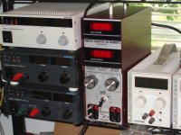
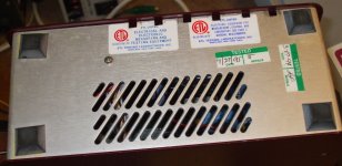
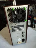
Some more pics of the Hoefer unit. The 1st pic shows the big insulated handle ON-OFF toggle switch I put on the Hoefer unit front in place of the stupid timer setup. The 2nd pic shows the bottom of the Hoefer unit, I added some extra vent holes along the edge, after slowing down the fan for quiet running. 3rd pic shows the Hoefer on the shelf with some Xantrex XT-250 supplies on the right side (for screen supplies, woops, the 120V model shown there) and some Xantrex XHR-600-2 supplies, stacked on the left side, for those heavy duty jobs. (0-600V, 1.7 or 2 Amps, a few thousand Watts there)
And also some pics (off Ebay, I don't have one) of an ISCO 494 Electrophoresis supply, which some have used before.
The ISCO 494 looks to be a 60 Hz Triac phase control design (similar to HP 6448 or EMI/Sorensen TCR-600) (big heavy boat anchors). Although the ISCO is slightly different in using a constant V power xfmr, which would make the phase control quite linear. (a square wave output, instead of a sine wave, from the XFMR)
Attachments

Last edited:
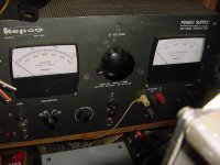
Nice report. A couple of years ago while walking around a local hamfest I spoted this LKB 2197 supply. Since it was later in the morning (I was there before 6AM) I assumed it was probably junk. But I asked the price anyway and was told five bucks. Jokingly I asked it it worked but didn't get a real answer. Bought it and stuffed it in the car and tried it out when I got back home. As suspected no output. But all the dials seemed to function as they should. After finding a manual on line I learned that you must have a second pair of banana plugs in the recessed jacks. Apparently there are optical sensors in the jack panel necessitating these for some safety reason I suppose. Perhaps the seller didn't know that. Maybe some day I'll find a use for it. I like my big humongous Kepco tube supply under the bench better. (0-600v/500mA) It's old but works every time I turn it on, even if it sits unused for a long time. It just won't die.
Attachments
Last edited:
I have a lot of different electrophoresis power supplies. Hoefer, Bio-Rad, Pharmacia. Those switch mode microcontroller supplies detect load parameters and may not work if they see something that doesn't look like electrophoresis chamber.
I much prefer analog-style electrophoresis supplies with power transformers. The smaller one, Model 250 (up to 250V 500 mA) is basically a transformer with switchable secondary taps, which feeds the rectifier. As simple as it gets. The second one, Fisher FB 650, is a 25 kg monster packed with iron. Can deliver 2 kV at 350 ma, or 6 kV at 100 ma. Constant voltage, constant current, or constant power modes.
http://s1045.photobucket.com/user/sser2/media/Supplies_zpswjtspeao.jpg.html?filters[user]=144240705&filters[recent]=1&sort=1&o=0
Last edited:
Yeah, these Electrophoresis power supplies are all over the place on specs: voltage, power and noise. They don't seem to care much about noise. Some of the old ones just had pulsating DC output. The newest ones have so many safety features and programmable operating modes, I would stay away from anything with an LCD screen for sure. But some of them are so cheap. No demand for used ones apparently.
Of course, I DO wonder about what kind of stuff has been spilled on these units. They are really streaked with gunk and spots. Level III containment stuff maybe? There was one flat head 6-32 screw in the cover of the Hoefer unit that required a MASSIVE torque to get it freed up. Some kind of penetrating corrosive that ate up the stainless steel screw!
Here are some more pics of the BIO-Rad 500/200, and Hoefer PS500-200 (linear supplies 500V, 200 mA, 100 Watt, about $120). And that mysterious LKB2197 (2500V, 250 mA, 100 Watt)($75). The linear units should be nice.
HP 6448 boat anchor and Kepco tube supply pics
..
Attachments
Last edited:
There is one sad aspect of low prices for used lab equipment: federal funds for research are getting more and more scarce, labs are closing, stuff going for pennies on a dollar. A good supply is $3-5K when purchased new. But, great opportunity for DIY, and these wonderful things are saved from scrap piles.
I wouldn't worry too much about dirt. In 99.99% of cases, it is completely innocuous.
I wouldn't worry too much about dirt. In 99.99% of cases, it is completely innocuous.
I managed to grab a Pharmacia EPS600 which seems working ok.
Any idea of where to get the power banana plugs which seem to be like longer than normal ones?
These sockets don't look easy to replace as the chassis is solid and everything needs to be removed from the back, bit by bit and the connectors are at the front of the unit. I don't want to modify this if I can.
Surely there are some standard electrophoresis cables that can be reused?
Any tips are much appreciated
Thanks
Ale
Unfortunately, these are non-standard connectors.
BIO-RAD Sub-Cell GT Wide Mini Electrophoresis Tray | eBay
These deep-reach banana plugs were purposely designed as safety feature. I can send you a cable salvaged from broken apparatus, you pay the postage.
BIO-RAD Sub-Cell GT Wide Mini Electrophoresis Tray | eBay
These deep-reach banana plugs were purposely designed as safety feature. I can send you a cable salvaged from broken apparatus, you pay the postage.
The Pharmacia LKB connectors on the EPS 500/400 unit I have here look to be 2 mm shrouded miniature banana plug jacks (European standard). With a deep recessed socket.
The Hoefer PS500X connectors are standard US 4 mm banana plug jacks. I use a US banana plug to 6/32 thread adapter to fit them. (for test bench clip lead attachment) (pics below)
2 mm banana leads:
2mm Banana Cables
The Hoefer PS500X connectors are standard US 4 mm banana plug jacks. I use a US banana plug to 6/32 thread adapter to fit them. (for test bench clip lead attachment) (pics below)
2 mm banana leads:
2mm Banana Cables
Attachments
Last edited:
I received the cable from Anatoly, unfortunately they don't fit but am looking into adapting the cable and glue it to the connector. The diameter is ok about 8mm and the depth of the socket is 28mm. I just glue the plastic section setting the depth to touch the internal connectors. Seems like the banana metal pin is too long.
Interesting topic. I have worked in a large clinical and environmental lab as a biomedical electronics technologist for over 30 years. We had a couple of those LKB supplies in our lab years ago. I remember repairing one of them. The biorads seem to be reliable. There are a lot of them scattered around the labs and I've only ever repaired one. The really old school supplies used tubes. I've seen KT88s used as outputs, 807s 6L6 etc. Most of those are gone now but I'm sure there are still a few of them sitting in cupboards. The old ones are a good source of transformers for tube amp projects.
Good lab practice would dictate that any equipment put out to surplus would be properly decontaminated before it leaves the lab. If you want to make sure, you can use a 10% solution of 5% household bleach to wipe down the power supply. It needs to remain wet for a few minutes to make sure the bleach does it's job. Since bleach can be corrosive you might want to wipe it down with mild soap and water afterwards. Wear gloves when doing this.
Good lab practice would dictate that any equipment put out to surplus would be properly decontaminated before it leaves the lab. If you want to make sure, you can use a 10% solution of 5% household bleach to wipe down the power supply. It needs to remain wet for a few minutes to make sure the bleach does it's job. Since bleach can be corrosive you might want to wipe it down with mild soap and water afterwards. Wear gloves when doing this.
Hello Smoking-Amp,
Based on your inputs, I have bought a Hoefer PS500XT from ebay. Seeing 115 and 230V models existed, I thought do not care and buy the 115V version, modify its input transformer connections to work on 230V... sadly no way it seems. I will buy an auto-transformer so I can hook it to my 230V mains. Tested it on a Variac and it works fine.
Do someone have a schematic ?
And then other questions:
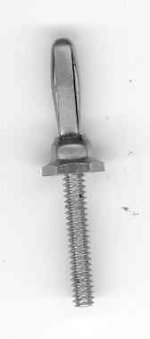
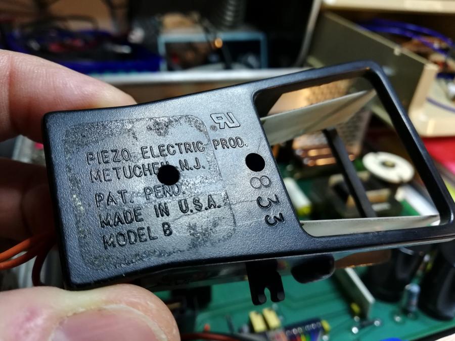
There is this strange device with two winglets, they vibrate when power applied. Seems its goal is move air around, like an internal fan or similar. It has got 3 connections, two orange wired together to the main power timer and a red one going to the PCB. What is its purpose and can I remove it ? I plan to add a fan anyway ?

I see on your pics someone has taken power for a small DC fan from the PCB. Can you explain where you connect it ? I can of course test around with a multimeter and see where I get a valid 7-8V or so, but hints will help...
thx !
Charles
Based on your inputs, I have bought a Hoefer PS500XT from ebay. Seeing 115 and 230V models existed, I thought do not care and buy the 115V version, modify its input transformer connections to work on 230V... sadly no way it seems. I will buy an auto-transformer so I can hook it to my 230V mains. Tested it on a Variac and it works fine.
Do someone have a schematic ?
And then other questions:
There is this strange device with two winglets, they vibrate when power applied. Seems its goal is move air around, like an internal fan or similar. It has got 3 connections, two orange wired together to the main power timer and a red one going to the PCB. What is its purpose and can I remove it ? I plan to add a fan anyway ?
I see on your pics someone has taken power for a small DC fan from the PCB. Can you explain where you connect it ? I can of course test around with a multimeter and see where I get a valid 7-8V or so, but hints will help...
thx !
Charles
Attachments

Last edited:
This is the one I have, no real current limiting, but really cheap
Can anyone help me modify this power supply? EC-135 ( OSP-135 ?) | Audiokarma Home Audio Stereo Discussion Forums
Can anyone help me modify this power supply? EC-135 ( OSP-135 ?) | Audiokarma Home Audio Stereo Discussion Forums
Thank you PRR. The piezo fan will go to the dodos and get a real fan installed instead. Preliminary tests confirm results of smoking-amp : the two large resistors get really hot and deserve a constant air flow !
Not sure about the airflow direction for the fan. Should I push air in, or pull air out ? There are large holes at the bottom of the case, so circulation is ok.
If there is a natural convection path from bottom to top then you should align your airflow with it. In other words, if there is generous ventilation on the bottom then have the fan pull air in through the bottom and exhaust out the back, assuming the fan will be on the back. The exception to this is if you had localized very hot parts in which case you would want to arrange the fan so that the coldest air possible was blowing directly on the hot parts. The piezo fan would really only provide air circulation within the case, so a fan that pulls air from outside is going to be much more effective.
Bfpca thanks for this logical explanation. Clearly it would make sense to pull air out, given the fan is at the top of the case, but the hottest resistors are right behind the fan air flow so I decided to pull in. Will see how it goes after a few hours loaded usage and a temperature sensor. Reversing is obviously easy.
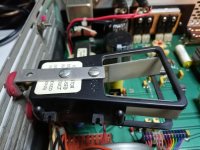
I placed the fan outside, because it's a little bit too small inside, with the large snuber resistors. The 12V fan is powered with 8V, pulled from the +15V opamp with a 3W/220Ω resistor in serie. It is not obvious from the pic, but I cut-out the aluminium grid to poke a large 50mm hole for good airflow.
I'm ordering a 300VA, 230/115V auto-transformer from Toroidy, and then it will be time to check the PSU under load and see what kind of CLC filter I add. Probably a small external box with input and output bananas sockets and the CLC filter in it, close to the circuit under test.
Not sure about the airflow direction for the fan. Should I push air in, or pull air out ? There are large holes at the bottom of the case, so circulation is ok.
If there is a natural convection path from bottom to top then you should align your airflow with it. In other words, if there is generous ventilation on the bottom then have the fan pull air in through the bottom and exhaust out the back, assuming the fan will be on the back. The exception to this is if you had localized very hot parts in which case you would want to arrange the fan so that the coldest air possible was blowing directly on the hot parts. The piezo fan would really only provide air circulation within the case, so a fan that pulls air from outside is going to be much more effective.
Bfpca thanks for this logical explanation. Clearly it would make sense to pull air out, given the fan is at the top of the case, but the hottest resistors are right behind the fan air flow so I decided to pull in. Will see how it goes after a few hours loaded usage and a temperature sensor. Reversing is obviously easy.
I placed the fan outside, because it's a little bit too small inside, with the large snuber resistors. The 12V fan is powered with 8V, pulled from the +15V opamp with a 3W/220Ω resistor in serie. It is not obvious from the pic, but I cut-out the aluminium grid to poke a large 50mm hole for good airflow.
I'm ordering a 300VA, 230/115V auto-transformer from Toroidy, and then it will be time to check the PSU under load and see what kind of CLC filter I add. Probably a small external box with input and output bananas sockets and the CLC filter in it, close to the circuit under test.
Attachments
Thank you PRR. The piezo fan will go to the dodos and get a real fan installed instead. Preliminary tests confirm results of smoking-amp : the two large resistors get really hot and deserve a constant air flow !
Not sure about the airflow direction for the fan. Should I push air in, or pull air out ? There are large holes at the bottom of the case, so circulation is ok.
>If there is a natural convection path from bottom to top then you should align your airflow with it.
>In other words, if there is generous ventilation on the bottom then have the fan pull air in through
>the bottom and exhaust out the back, assuming the fan will be on the back. The exception to this is
>if you had localized very hot parts in which case you would want to arrange the fan so that the
>coldest air possible was blowing directly on the hot parts. The piezo fan would really only provide
>air circulation within the case, so a fan that pulls air from outside is going to be much more effective.
Bfpca thanks for this logical explanation. Clearly it would make sense to pull air out, given the fan is at the top of the case, but the hottest resistors are right behind the fan air flow so I decided to pull in. Will see how it goes after a few hours loaded usage and a temperature sensor. Reversing is obviously easy.
I placed the fan outside, because it's a little bit too small inside, with the large snuber resistors. The 12V fan is powered with 8V, pulled from the +15V opamp with a 3W/220Ω resistor in serie. It is not obvious from the pic, but I cut-out the aluminium grid to poke a large 50mm hole for good airflow.
I'm ordering a 300VA, 230/115V auto-transformer from Toroidy, and then it will be time to check the PSU under load and see what kind of CLC filter I add. Probably a small external box with input and output bananas sockets and the CLC filter in it, close to the circuit under test.
Mmh I think there is a serious bug in the forum software, last post is half from me, half from Bfpca. Probably some strange edit/quote/reply combination that had Bfpca's session associated with my own session. Not very important to me, but maybe the forum software needs an update.
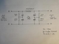
CLC filtering for Hoefer PS500XT
Hello again,
I realize I have so much to learn... I'm very grateful for your help !
smoking-amp told about the lack of good filtering for the Hoefer PS500XT. My intended use is to experiment tube amp circuits with this PSU. I can well imagine I want it to be stable and not introduce noise into my circuit under test (my model has an EMI input filter on the main so I have no plan to modify this side).
So my idea is to add some filtering at the output, in a distinct chassis. Will a CLC filter be appropriate ? Looking at Toroidy page, they have this 12H/400mA /66Ω DC choke, which I would preceed and follow by two set of electrolytic capacitors, twice 400V in serie with bridge resistors would be safer. The resistors would serve as bleeders as well.
What I'm not sure :
- is it a problem (beside weight, price) to have such a high-current DC choke, which I will probably never saturate ?
- what size of capacitors should I use ?
- do I need to snub the electrolytics with small caps ? If yes, what types should I prefer ?
Attachments
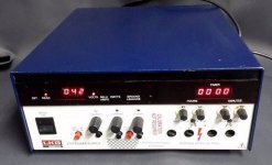
I have two ISCO power supplies. One is a model 494 which I've only tested to make sure it works and functions correctly. The other one is a ISCO model 470 which has digital displays and it sees usage when I am working on a design.
The last unit is a Dan Kar that is capable of 2000volts @ 200 mA. Its a no frills unit that consists of a transformer a variac and a heck of a bank of capacitors.
Out of the three I use one. The others will probably get tossed when we sell the house and move.
The last unit is a Dan Kar that is capable of 2000volts @ 200 mA. Its a no frills unit that consists of a transformer a variac and a heck of a bank of capacitors.
Out of the three I use one. The others will probably get tossed when we sell the house and move.
- Status
- This old topic is closed. If you want to reopen this topic, contact a moderator using the "Report Post" button.
- Home
- Amplifiers
- Tubes / Valves
- A look at some Electrophoresis HV power supplies