Bought cheaply as it had an intermittent power fault.
Technics SA-GX690.
Would switch on (but the speaker relay would not kick in) excepting one in forty presses of the power button. Once on it worked as expected with no other faults or aberrations. 🙂
Once on...if left for some hours (80+) it would re-power the relay if switched off and back on again....
If left off for 24 hours the initial fault reappeared.
So... my limited knowledge, as a total amateur, best guess was a component failure in the timing circuit for the speaker relay.
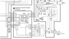
Finally tracked down a service manual/schematic and saw the capacitor #C753 25v 1000mFd in the relay circuit that might have a relationship to timing and checked it by replacing with a good known one.... Fixed ! 😀
Looking at the cap and its placement it would seem the fan hole dictates the capacitor size and so a small cap that fails quickly was chosen over a larger and more reliable unit.
At least I will know to check and replace in future for this otherwise useful amp.
Hope this helps any others with the same problem.
Even a blind squirrel finds an acorn now and then....
Best,
Bob.
Technics SA-GX690.
Would switch on (but the speaker relay would not kick in) excepting one in forty presses of the power button. Once on it worked as expected with no other faults or aberrations. 🙂
Once on...if left for some hours (80+) it would re-power the relay if switched off and back on again....
If left off for 24 hours the initial fault reappeared.
So... my limited knowledge, as a total amateur, best guess was a component failure in the timing circuit for the speaker relay.
Finally tracked down a service manual/schematic and saw the capacitor #C753 25v 1000mFd in the relay circuit that might have a relationship to timing and checked it by replacing with a good known one.... Fixed ! 😀
Looking at the cap and its placement it would seem the fan hole dictates the capacitor size and so a small cap that fails quickly was chosen over a larger and more reliable unit.
At least I will know to check and replace in future for this otherwise useful amp.
Hope this helps any others with the same problem.
Even a blind squirrel finds an acorn now and then....
Best,
Bob.
Attachments
Last edited:
I may be dining on minimal nuts this winter..🙁
My fix was no fix at all.
Damn intermittent faults..
Having been through the schematic and tested what I can with a multimeter....
Here is the problem...Amp switches on and either the speaker relay/s kick in after a short delay...or they don't.
When they do they may work for some time (10-30 minutes) then drop-out or 'rattle on/off on/off on/off"
Whilst the display shows the correct speaker selection the relays don't select.
When the relays don't operate there is no measured voltage to them.
As all relays are affected it appears to be a power issue rather than individual relays or their driver circuitry.
When the test of the fan is used (select a radio preset and increase volume control to activate fan) the relays oscillate as the fan engages.Once the fan is running they stay in the off mode.
Again it points to a power supply issue ?
I have tested the diodes and resistors in the relay power circuit and they are all good.
Any and all suggestions appreciated...😀
Cheers,
Bob.
TECHNICS SA-GX690 SERVICE MANUAL Pdf Download | ManualsLib
This kind of problem can often be found with a $25 DVM and a schematic, but there are almost 50 v running around in there, which could stop your heart if it runs from one hand to other. Buy some alligator clip leads to tie the negative probe to analog ground (w701 pin 10) or the tie point of C705 C706. then use one hand to look at some voltages. C705 C706 + & - is where I would start. I'd then look at any low voltage supply for op amps or input stages, and I'd look at music going into the protection relay for DC voltage. Haven't looked at the schematic, leaving it up to you. But electrolytic capacitors are known to be tired at >10 years of age. also could be bad solder joints (how long have you owned this? did it work great 10 years then go bad? not solder joint) or oxidized connections between boards (remove & replace to scrape off copper/tin oxide).
Best of fortune.
Best of fortune.
Last edited:
Thank you for the pointers.
I replaced C705 C706 with some junk box spares and the problem persists. In fact seems to be more pronounced as the replacements are larger value than currently installed.
However...resorting to percussive maintenance has revealed that your comment re a bad solder joint may be worth following. A good bash upon the first relay prompts it to work correctly.(For a little while..so presumably this is not a protection circuit fault I'm tracking)
Plan now is to inspect and rework the solder joints pertaining to the relay/s.
I am still a little confused though as to why the fan test causes the relays to chatter as the fan is on a different supply line to the relays.
If this fails I will be stripping for parts and cutting my losses.
Thanks again for the direction.
Progress.. sort of.
Re-soldered around the relays and their associated components, Used my multi-meter to check voltages as per the schematic...all correct.
Re-seated all internal power cables and plugs.
Re-installed original C705 C706.
Visual inspection of board shows no obvious damage to any small components nor any cracks or track damage.
Replaced a couple of small caps around the relay driver transistors just in case and reassembled to test...
Same fault. No change.
Pressed down on Relay #1 whilst testing and everything behaves as it should. Loosened nearby screw holding the main board to the heatsink and ...voilà !! Behaves as it should !! Soak testing currently.
Thoughts at this stage are that the amp has been 'lightly' dropped at some stage prior to my acquisition and an output module has lost connection on one of its pins (no, I never checked those because..)
This would explain the random nature of the fault...why when it is ok it subsequently drops out after some time...(Heat expansion) and why walloping or pressing down rights things.. (re-contact is made...'calling occupants of interplanetary craft' etc) and why the fan causes problems...(vibration !)
So, next step is to re-solder the output module pins nearest the #1 Relay...🙂
The fan will cause some mechanical vibration, however slight, which may have worsened as its resilient mounting material aged but its control circuit may still affect the power to other circuits, depending on the reliability of other common connections, such as ground and occasional details like loose connecting wires that vibrate in the air current. If operation is marginal due to the small electrolytic capacitor story, you still could have the problem there.
Don't guess though, clip a voltmeter or three directly on the supplies to the fan and protection chips to continuously monitor what's happening there with each event. There are +/-56, +/-28 voltages applied directly to the ICs there, so I'd not only be careful but suspicious that they may have developed internal faults.
Note that being protection chips, they are supposed to cut relay power when there is fault current or voltage, so it would be logical to check for any DC voltage, brief or constant, you have at both amplifier output connections as you try to power up.
A problem that seems to be so random though, doesn't point to capacitors but to logic circuits and connections, not just solder connections but crimped wires and any little multi-pin strip connectors used to inter-connect various PCBs and various sections of a main board. You probably tried this, but pulling and reinserting the plugs can occasionally bring circuits back to reliable state, due the effects of loose, dirty or poor assemblies and crimps that didn't show up in production tests. ...
Edit: ah, missed your post and you seem to have been at the connections already....Good work!
Last edited:
Thank you Ian for the good tips.
3 hours and counting on soak test so things are looking up.
I purchased this amplifier from our local recycling depot...
having seen how items are treated during and after 'drop-off' I have no doubt as to how it has been 'cared for'....
just took me a while to realise that the fault could indeed be mechanically induced rather than an electronic failure.
Last edited:
The screw to heat sink may be an oxidation due to the years thing. If they expect a screw to conduct "ground" to the heat sink, aluminum is bad to oxidize. On these things I use stainless steel star washers under the screw to bite into the metal - available in boxes of 50 from mcmaster and grainger.Progress.. sort of.
Visual inspection of board shows no obvious damage to any small components nor any cracks or track damage.
Replaced a couple of small caps around the relay driver transistors just in case and reassembled to test...
Same fault. No change.
Pressed down on Relay #1 whilst testing and everything behaves as it should. Loosened nearby screw holding the main board to the heatsink and ...voilà !! Behaves as it should !! Soak testing currently.
Thoughts at this stage are that the amp has been 'lightly' dropped at some stage prior to my acquisition and an output module has lost connection on one of its pins (no, I never checked those because..)
This would explain the random nature of the fault...why when it is ok it subsequently drops out after some time...(Heat expansion) and why walloping or pressing down rights things.. (re-contact is made...'calling occupants of interplanetary craft' etc) and why the fan causes problems...(vibration !)
So, next step is to re-solder the output module pins nearest the #1 Relay...🙂
There are also special grounding washers with a machined surface, but the person that revealed them to me didn't tell how to buy the things other than a pallet of boxes of them from the manufacturer.
Random parts replacement without taking measurement sometimes hurts things. My bad solder joint rate is about 10% and I've been doing this for 50 years. Quality up a bit since I bought a $50 vary temp iron last year. Pushing on solder joints with a meter probe with the power on can reveal where a bad joint or connection is, also.
As Mr Finch said, push in connectors like ribbon or amp KKR are very prone to oxide block of low voltage low current signals like "ground" at > 10 years. Remove & replace wire in the clip to scrape oxide off those.
Last edited:
- Home
- Amplifiers
- Solid State
- A little knowledge sometimes works...SA-GX690