When you were working on the MX50X2 I assume you adjusted the bias currents?
If so, where did you put the potentiometer? Did you lift one end of one of the resistors and put it in series or did you put a larger potentiometer in parallel over one of the resistors?
What bias current did you like best?
If so, where did you put the potentiometer? Did you lift one end of one of the resistors and put it in series or did you put a larger potentiometer in parallel over one of the resistors?
What bias current did you like best?
I think I replaced one of the bias setting resistors with a trimmer. I never liked it, independent of Iq.., but higher was better as far as I remember.
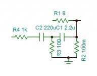
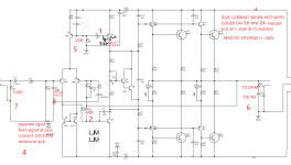
So far I have placed an RM065 2k trimmer in place of the lower 2.2k Ohm bias resistor. (Marked in red on the attached schematic. Note that the resistor values on the schematic do not match what arrived on my board.)
I have set 55 mA for the inner pair of transistors. (24 mV across the two series 0.22 Ohm resistors.) On both boards I have noticed that the inner output pair runs at higher bias than the outer pair by a fair bit. Perhaps 35 mA on the outer pair and 55 mA on the inner pair.
So I am running a little less than 100 mA bias per amplifier with the two pairs of outputs.
I also replaced the 10uF 50V FW input coupling cap with a Nichicon UES I had left over from upgrades to the caps in my Denon AVR-3805.
What rail voltages did you use with the MX50x2? I ask since one of the two all stock MX50x2 boards blew the outputs, drivers, two 100 Ohm, two 470 ohm and three of the four 0.22 ohm resistors in seconds at idle on +/- 50V the first time it was powered up at +/- 50V. The other board was fine.
Not sure if it was due to poor quality components, fake outputs or drivers or significantly mismatched outputs and/or drivers.
Both boards had been used without issue for some time at +/- 20V from my initial "easy test" setup supply (LM317 & LM337).
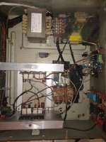
Attachments
Last edited:
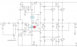
Solder a small ceramic capacitor 3.3 pf to trs Q6 (5401) on the legs underboard.This solve oll of your problems.Powe supply under +- 42 v dc.Also separate the signal gnd from the power gnd on the pcb.With a thin wire connect the gnd of big power capacitors psu to the common source signal gnd on the potensiometer.Idle current 15ma per one transistor at (+) side of the board.
Attachments
Last edited:
I'm sorry, but this does not look like a good mod IMHO..
I had a 'blameless' amp with a similar CCS setup, and had rise time problems and overshoot on the positive flank because of too high capacitance in that transistor, so adding capacitance here does not seem like a good idea. This cap will also couple transients to the input CCS. Possibly adding a capacitance from the base to + supply rail would be an option.
In the blameless amp, changing to a faster transistor solved that problem.
Looks like there is parts missing in that schematic also?
My MX50x2 amps are scrapped for parts by now.
Last edited:
I can try a 3.3pF and I can also try a different transistor.
What would be a more suitable transistor to use?
My MX50X2 are still assembled and I just spent the last week comparing them with my MX50SE. I think that the MX50SE sounds better than the MX50X2. I used 2SC5200N/2SA1943N outputs, 10k and 1k for the feedback resistors and a 2k 3296 trimmer for the bias setting.
Next I plan to compare some more with my finished DIY MA-9S2 and later with in-progress next projects (KSA50, FH9 and L20.5).
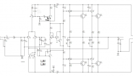
I've run a simulation of the circuit as posted in #1/#2. it is unstable in my sim showing slight HF oscillations in the diff amp stage - not visible in the output! - with a resistive load, but I used BD139/BD140 drivers and TIP3055 op. It needs some work to correct. It is possible, but there are other "not so good points"
- no resistors in the current mirror emitters. May not give a good balance.
- quasi complementary but the lower output stage has diodes connected to the centre rail. diodes and their shunt resistors should be to the collectors of the output transistors.
I also recommend using separate CCS for the vas load and diff input stage. reason is that the VAS stage should not load or affect the input stage, and separating the two bases by a resistor is not a good idea, as you want the base impedances of the CCS to be as low as possible.
Don't need to change the power transistors,you must not.Just do the little modifications above.It is far better than mx50se board,it will be very smooth-crystal.
I had to change the output transistors because the D1047 incinerated and took out a bunch of other components.
Right now I have 2SC5200N (genuine Toshiba from Mouser (authorized distributor)) installed.
I ordered D1047 from AliExpress and the quality is too poor to use (wildly varying hFE and rapidly decreasing hFE with Ic in 1 to 3A range).
Since the original D1047 are dead are you suggesting that I should try to get real/quality D1047 (such as STMicroelectronics 2SD1047) instead of the 2SC5200? I don't see any authorized KEC distributors here.

- Home
- Amplifiers
- Solid State
- A little help solving stability on a MX50X2?