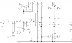
As I understand it, this a clone of the MF XA-50 made by LJM. The version of the board I have is green, and was indicated somewhere as the second and improved clone by LJM.
I hope somebody can give some guidance on how I can improve the overshoot/stability on these amps. I had them for some time, and did not like the sound much (bass was good, but the rest sounded harsh..) so they were left in the scrap box. I'm hoping the issue is the overshoot/ringing, because they measure ok on distortion measurements.
I played around with one of the boards on the scope with square input, and the things I found are:
-Massive oscillation with 0.5uF parallell to 7,2ohm load. Added a LR on the output, and there is ringing, but it is damped.
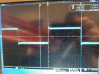
-Overshoot on the flanks with 4k square wave. Hardly visible with no load, but gets worse with lower loads and higher output voltages.
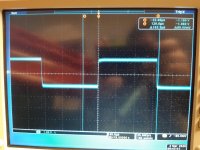
I attached some pictures with schematic and some scope shots with 1,8ohm load and no LR(worst case), 7,2ohm & LR(better), and one without load(pretty good).
So, the question is what should I try to tweak? When it comes to compensation and ringing, I'm pretty much clueless.. but maybe I can learn a little with some help here, and at the same time get a usable amp?
I hope somebody can give some guidance on how I can improve the overshoot/stability on these amps. I had them for some time, and did not like the sound much (bass was good, but the rest sounded harsh..) so they were left in the scrap box. I'm hoping the issue is the overshoot/ringing, because they measure ok on distortion measurements.
I played around with one of the boards on the scope with square input, and the things I found are:
-Massive oscillation with 0.5uF parallell to 7,2ohm load. Added a LR on the output, and there is ringing, but it is damped.
-Overshoot on the flanks with 4k square wave. Hardly visible with no load, but gets worse with lower loads and higher output voltages.
I attached some pictures with schematic and some scope shots with 1,8ohm load and no LR(worst case), 7,2ohm & LR(better), and one without load(pretty good).
So, the question is what should I try to tweak? When it comes to compensation and ringing, I'm pretty much clueless.. but maybe I can learn a little with some help here, and at the same time get a usable amp?

Attach your loudspeaker as load and see the square wave. Adjust any C7, C4, C5. I doubt the harshness is due to stability. The quality of C1&C6 can be the cause. Short them and listen (with offset maybe ) . You can add a current feedback by adding a 0.1 ohm resistor in series with the -speaker_ ground and bring the ground of C6 to -speaker_ 0.1ohm joint.
Thank you for the input! I started removing the capacitors step by step, and tested with each step (only resistors as load). After removing, I put them back again, and tested again, and everything was suddenly fine! It turns out the input GND had a bad connection, and without the input GND, there was the overshoot.
Now I have done some more testing with a good input GND, and I really cant see any benefit from the 5p C5. I tested with 1,8ohm and get a little overshoot, and also with 0,5uF in parallell, and it's still very stable with just a little overshoot (like the middle picture).
However, this does not explain the 'bad sound', since I listened to them in a completely different setup, with good cables.
I must say I have never heard 'capacitor sound', except when I changed to other values of capacitors. This makes me a little reluctant to try that..
However, you made me curious about the 'current feedback'. Do you have some links to some discussions/tests on this?
I did a quick simulation with this on a JLH I had in LTspice, with a step input and LR load. I see the voltage spikes first to try to drive current in the inductor, and after it settles.
It reminds me a bit of when I did a test with a dual coil woofer, and used the second coil as 'motion feedback' and injected the signal from the second coil into the feedback path of the amplifier. It also gave a similar step response, boosting the flank to accelerate the membrane.
I'm now trying simulation with a RLC load, but it seems to take forever to run the simulation.. I guess this is a sign of the complexity of amps working with reactive loads..
The current feedback linearizes the output impedance, and at high frequencies it transformers the inductive nature of the voltage feedback into capacitive. But it decreases the DF. DF values above 16 is not necessary . Q7 669 what is it?
My brain is trying to comprehend the impact of the current feedback.. it would also mean that the speaker impedance varying with frequency would impact the frequency response, since voltage will vary with impedance?
I was hoping to do some experiments with compensation capacitors and measure distortion, but can't find my box with small capacitors. I could see stuff happening on the scope while adjusting Iq and connecting/disconnecting the C5, it seemed more linear with cap in at low Iq, and more linear with cap out on 'sufficient' Iq setting..
Maybe I will just leave out the C5 and try the amps like that. I have some better bipolar caps I could use for the feedback cap too. However, I still doubt it will make me like the amp.. Maybe I'll even try the current feedback for fun.
I'm not sure what you mean with the Q7 question? If you don't know what it does, I surely don't! I'm just the apprentice! 🙂
What reference is the transistor ? BC669 ? The current feedback does higher the output impedance but it still remains bellow 0.5 ohm , the impedance variation doesn't effect much to the output voltage.
Last edited:
A good sound amp need good sound transistor, transistors in good work condition(current flow) and circuit with suitable coupling capacitor.
This amp transistors using low current, so that the amp sounding will be not good.
This amp transistors using low current, so that the amp sounding will be not good.
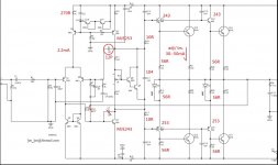
If you triple the differential current, you triple the gain and make the amp unstable. To keep the designer's option better use low current 2sa992 instead of 5401. What do you know about 669? Mje243 is a high current low Ft transistor, much finer ones are 2sc2705 (Pioneer) and 2sc3423 (Marantz). No need to change the CCS and the drivers.I would like to test it as below, if still no good sound then maybe give up this circuit
What reference is the transistor ? BC669 ?
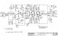
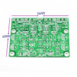
The transistor is actually marked NCC 5551.
The schematic and the actual board do not have the same transistors..
I attach a picture of the board.
Attachments
I have tried the current feedback with a 0.1ohm resistor to GND on the bench using only resistors as load.
I can see that distortion goes down a bit. I guess this is due to more feedback (load dependant).
However, I'm suspicious to the concept, because I see that varying the load between 5,6 to 6,4 ohms, makes 1dB diffrence in the output.
The impedance on my speakers is varying between 3,3 ohm and maybe 15ohms at some frequencies.
So, it seems that I get -3,3dB with 6,4ohm load, -4,3dB with 5,6ohm, and I guess close to 0dB at 15ohm. This means the frequency response from the speaker would vary a lot..
If I make a wild guess.. this would be equal to a 3,4ohm resistor in series with the speaker? Feedback divider is 33k/1k, and if I multiply the 0,1ohm resistor (to GND on the feedback cap) with 34, that would be the same as using a series 3,4 ohm resistor?
You must decrease the 0.1 ohm or apply 100ohms potentiometer across it and capture the center point to the feedback capacitor. By this you can adjust the output impedance . Most important , how does it sounds with current feedback as it is now? In most cases , with current feedback you don't need any Zobel or L/R on the output.
I have not listened to it, I have only done some tests on the bench to see how it behaves. I could see to that it's absolutely stable with a 0,5uF across the load and square wave.
Ok, a potentiometer is an interesting approach to adjust the output impedance.
I can also see that IMD is not great on this amp with multitone input. Distortion is rising with frequency. Also on single sine input, it has a lot of high order distortion components. Maybe that is why I don't like the sound from it.
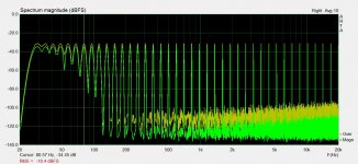
I have installed the potentiometer on one channel, and did a multitone FFT with the 'current feedback' potentiometer at one end and the other.
In the standard position it is the worst I have seen. I think I never saw an amp where this signal to 'distortion noise' was less than -80dB. Here it is close to -60dB, and then improves to a 'tolerable level' with the full current feedback.
This should make the amp sound cleaner.
In the standard position it is the worst I have seen. I think I never saw an amp where this signal to 'distortion noise' was less than -80dB. Here it is close to -60dB, and then improves to a 'tolerable level' with the full current feedback.
This should make the amp sound cleaner.
Attachments
I have quickly listened to it on my 'easy load' 8ohm speakers. I can't say I liked it much in the current feedback mode. Bass was not good, booming low frequencies and somehow 'slow' sounding. Seemed midrange was more dominant, and that would be explained with an impedance peak at XO frequency. Maybe the treble sounded a bit 'smoother' but that's about all the positive I could hear.
On the other hand I had an idea that the problem with the amp could have something to do with grounding paths on the pcb. This is because IMD seems to rise quickly with more output current. It's quite ok around 1W, but rises pretty quick after that. I adjusted the Iq just to see that it's not because it's going from class a to class b, and it does not seem so.
Maybe it would be worth a try to isolate the low current ground and high current ground..? I'm thinking 'ground breaking resistor' to the low current ground, if it's easily done on the pcb.
I have rebuilt them to the original setup, except new input and feedback capacitors that I replaced earlier when I tried the current feedback.
Measurements look fine again, including IMD with multitone, where the signal to distortion floor is now close to 90dB at a pretty wide output range. There is some low level high order distortion, also showing up high in the audio band with IMD measurements though.
There must have been some side effects of the soldered on components for the current feedback, giving the results I posted above, because now it looks a lot better again.
I have been scoping for current spikes on the emitter resistors and oscillations, and it all seems fine to me.
I don't know what to make of this. Another waste of time I guess, but hopefully learning something along the way.
At least one thing I have confirmed (again), an amplifier that measures fine, does not always sound good to my ears. It is not a satisfying conclusion though.
Welcome to the planet of Audiophiles.I have rebuilt them to the original setup, except new input and feedback capacitors that I replaced earlier when I tried the current feedback
At least one thing I have confirmed (again), an amplifier that measures fine, does not always sound good to my ears. It is not a satisfying conclusion though.
- Home
- Amplifiers
- Solid State
- A little help solving stability on a MX50X2?