I present a reasonably simple complementary headphone amp which should be able to drive most dynamic headphones out there. I was inspired to build it by my recent acquisition of some nice IEMs with 16-ohm impedance. My primary headphone amp was designed for high-impedance headphones and suffers when driving the 16-ohm load. This new amp will drive all my headphones with ease.
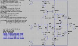
The absence of source resistors on the JFETs and MOSFETs and use of current feedback is, of course, inspired by the F4 Beast (which, in turn, is inspired by the XA25, and Nelson Pass' BAF2016 talk), while the use of a current mirror is inspired by the original UGS stage and subsequent UP amplifier by CheffDeGaar. As I understand it, based on comments by Nelson Pass and CheffDeGaar, both modifications should bring about a very natural sound with very low distortion.
I initially experienced thermal runaway, so added the thermistors to keep everything in check. This works fantastically and is simple to implement. I used 4.7k thermistors since I had them on hand, but the resulting bias is a little lower than desired. Perhaps a slightly larger value would be better. One could also use their favorite Vbe multiplier circuit.
R14 is an added "safety" feature to prevent shorting the output to ground when plugging and unplugging headphones. Shorting the output directly to ground could cause damage to the MOSFETs. If you use some sort of XLR connection, R14 can probably be safely omitted.
Input JFETs should be GR-grade, 4-5mA IDSS or so. If you use higher IDSS JFETs, adjust R7 and R8 to allow less current through Q2 and Q4. Target current through these transistors is 8-12mA. Of course, the current mirror transistors should be thermally coupled.
This amp is (obviously) DC coupled on both the input and output, so extreme care should be taken to avoid high DC offset. I cannot be blamed for damage to your headphones, if you build this amp and fail to take precautions. My source has ~6-8mV DC offset, which causes the output of the amp to have ~35-50mV of DC offset. This can easily be trimmed off by adjusting P1. Once trimmed, the offset is very stable and wanders maybe +/-5mV at most as the amp warms up. Offset varies +/-30mV when the amp is powered on or shutdown, so I recommend not having headphones plugged in during the first few seconds after these events.
Should anyone build this amp, I recommend doing the initial power-on without the output FETs in place. Then, adjust P1 until you have roughly 4.3V or so at both gate pads for M1 and M2. This avoids any potential unpleasantness in the event P1 is too far up or down.
Power supply can be essentially whatever you want, +/-12V to +/-24V, as long as the dissipation through Q2, Q4, M1, and M2 is reasonable. I aimed for about 2W dissipation on M1 and M2, for a ~10C rise over ambient on heatsinks.
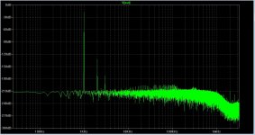
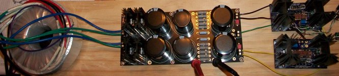
I have attached pictures of the circuit, simulated FFT at 1mW RMS into 16-ohm load, the amp as currently built with borrowed mini-aleph power supply (at +/-17V instead of the +/-15V on the schematic), and a close-up of the boards I had made by OSH Park.
Finally, the sound... I am not great with audiophile banter. The amp sounds very nice. Very natural sound. It is clean and clear over the entire spectrum. It just seems to "let the music through," as I have heard others say in amp reviews. Perhaps more words will come to me as I listen more...
The absence of source resistors on the JFETs and MOSFETs and use of current feedback is, of course, inspired by the F4 Beast (which, in turn, is inspired by the XA25, and Nelson Pass' BAF2016 talk), while the use of a current mirror is inspired by the original UGS stage and subsequent UP amplifier by CheffDeGaar. As I understand it, based on comments by Nelson Pass and CheffDeGaar, both modifications should bring about a very natural sound with very low distortion.
I initially experienced thermal runaway, so added the thermistors to keep everything in check. This works fantastically and is simple to implement. I used 4.7k thermistors since I had them on hand, but the resulting bias is a little lower than desired. Perhaps a slightly larger value would be better. One could also use their favorite Vbe multiplier circuit.
R14 is an added "safety" feature to prevent shorting the output to ground when plugging and unplugging headphones. Shorting the output directly to ground could cause damage to the MOSFETs. If you use some sort of XLR connection, R14 can probably be safely omitted.
Input JFETs should be GR-grade, 4-5mA IDSS or so. If you use higher IDSS JFETs, adjust R7 and R8 to allow less current through Q2 and Q4. Target current through these transistors is 8-12mA. Of course, the current mirror transistors should be thermally coupled.
This amp is (obviously) DC coupled on both the input and output, so extreme care should be taken to avoid high DC offset. I cannot be blamed for damage to your headphones, if you build this amp and fail to take precautions. My source has ~6-8mV DC offset, which causes the output of the amp to have ~35-50mV of DC offset. This can easily be trimmed off by adjusting P1. Once trimmed, the offset is very stable and wanders maybe +/-5mV at most as the amp warms up. Offset varies +/-30mV when the amp is powered on or shutdown, so I recommend not having headphones plugged in during the first few seconds after these events.
Should anyone build this amp, I recommend doing the initial power-on without the output FETs in place. Then, adjust P1 until you have roughly 4.3V or so at both gate pads for M1 and M2. This avoids any potential unpleasantness in the event P1 is too far up or down.
Power supply can be essentially whatever you want, +/-12V to +/-24V, as long as the dissipation through Q2, Q4, M1, and M2 is reasonable. I aimed for about 2W dissipation on M1 and M2, for a ~10C rise over ambient on heatsinks.
I have attached pictures of the circuit, simulated FFT at 1mW RMS into 16-ohm load, the amp as currently built with borrowed mini-aleph power supply (at +/-17V instead of the +/-15V on the schematic), and a close-up of the boards I had made by OSH Park.
Finally, the sound... I am not great with audiophile banter. The amp sounds very nice. Very natural sound. It is clean and clear over the entire spectrum. It just seems to "let the music through," as I have heard others say in amp reviews. Perhaps more words will come to me as I listen more...
Attachments

Last edited:
Thank you, ZM. I had hoped that this might garner some attention by others because of the recent popularity of headphone amps, but perhaps I misread the waters...
Anyway, a couple more words about its evolution: I initially planned an entirely scaled down F4 Beast with a VFET2-like front end using ZVP/ZVN3310 MOSFETs without source resistors as drivers. I abandoned this approach for three reasons:
1. Two trimpots are necessary to set the operating point and zero front-end offset and simulations showed the trimpots may be touchy.
2. My prior experience with the 3310's showed them to wander substantially with temperature fluctuation.
3. Eliminating the capacitors coupling the front end to output stage made offset adjustments look even more touchy in SPICE.
I found the simplicity of the single trimpot with the current mirror version very appealing. The elegance of this approach (due to CheffDeGaar) won me over, despite the slightly better (simulated) performance of the all FET version.
In the future, I plan to test a version using Alfet laterals on the output. With their zero temperature coefficient at ~120mA, they may just be the perfect output devices for this kind of amp.
Now to do more listening, take some measurements, and get it all cased up...
Last edited:
I like it. Might get a little more attention (and it should) in the headphone amp section instead of the pass labs forum. I might try it if I can get bl grade jfets too work.
Yes, it's a nice sounding circuit. It has been mentioned in Pass HPA-1 thread (post #10) and it's very versatile - you can make it into power amp or different kind of preamps, there's a lot of room for experimenting. 
Might get a little more attention (and it should) in the headphone amp section instead of the pass labs forum.
I debated about where to post and settled on Pass Labs since two circuits detailed in this forum inspired the amp, but you are right that the headphone amps section may be a better fit.
Yes, it's a nice sounding circuit. It has been mentioned in Pass HPA-1 thread (post #10) and it's very versatile - you can make it into power amp or different kind of preamps, there's a lot of room for experimenting.
Ah, I figured the circuit was simple enough that it had to have been posted somewhere before. Indeed, your circuit in that thread is essentially the same as what I used.
Why would you want to ue R11 if you are using NFB (R5/R6) ?
Perhaps you can also try just using R11 (of an appropriate value) and skip NFB altogether.
We had a similar circuit with a diff pair front end, but preferred 2K1058/2SJ162 for the output.
The zero tempco is at ~0.6V 100mA.
So thermally stable even without R_source.
http://www.diyaudio.com/forums/pass...ce-follower-configurations-9.html#post4904152
Patrick
Last edited:
R11 loads the the gm stage and defines the OLG that way. Of course, the feedback loop is not necessary but many will say that this circuit sounds better with it...
Why would you want to use R11 if you are using NFB (R5/R6) ?
Perhaps you can also try just using R11 (of an appropriate value) and skip NFB altogether.
It will be interesting to try out different combinations of values of R11 with and without NFB, as you suggest. The circuit is cheap enough to build that I might just try out a few different variations and compare them directly.
We had a similar circuit with a diff pair front end, but preferred 2K1058/2SJ162 for the output.
The zero tempco is at ~0.6V 100mA.
So thermally stable even without R_source.
I'll look into trying those as well. As usual for an initial test, I chose to use parts I had on hand. Unfortunately, I don't have any laterals in stock. Now that I am satisfied that the circuit works and sounds good, I can start experimenting with more exotic parts.
Last edited:
Very nice implementation indeed needtubes !
Would you mind posting the .asc so that we can have a fiddle ?
Would you mind posting the .asc so that we can have a fiddle ?
Very nice implementation indeed needtubes !
Would you mind posting the .asc so that we can have a fiddle ?
Certainly, see attached.
Attachments
Just for you to play around with. Not prototype tested.
You can change the amount of NFB by changing the value of R5, including leaving it out altogether.
Patrick
.
You can change the amount of NFB by changing the value of R5, including leaving it out altogether.
Patrick
.
Attachments
Last edited:
Certainly, see attached.
there is a connection lost at R3.
To the pos rail?
And just for fun, here an all-FET version with zero global feedback.
R21 is added to trim 2nd harmonics of the output stage.
(2SJ162 has somewhat lower Yfs at bias.)
Very low distortion at 1Vrms into 30R, without NFB.
Patrick
.
R21 is added to trim 2nd harmonics of the output stage.
(2SJ162 has somewhat lower Yfs at bias.)
Very low distortion at 1Vrms into 30R, without NFB.
Patrick
.
Attachments
there is a connection lost at R3.
To the pos rail?
i just use 35R to connect to the +ve rail - sims great.
Its a nice implementation and someday I'll get round to scaling up for a power amp..thx needtubes 🙂
And just for fun, here an all-FET version with zero global feedback.
R21 is added to trim 2nd harmonics of the output stage.
(2SJ162 has somewhat lower Yfs at bias.)
Very low distortion at 1Vrms into 30R, without NFB.
Patrick
.
very impressive patrick 🙂🙂
somebody is going to make this into the ultimate linestage !!
- Status
- Not open for further replies.
- Home
- Amplifiers
- Pass Labs
- A headphone amp inspired by F4 Beast and UGS/UP