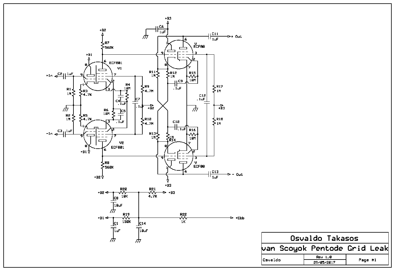
Since some time ago I have the idea of to experiment the van Scoyok phase splitter, but using as the second stage, a pentode. It is true and well known that a pentode can give us a better amplification and lower distortion than a triode, at the expense of some more partition noise than the latter. Also, I had from recovering from TV tuners, some interesting triode-pentode like the ECF801 and 6CG8, created for low noise and high transconductance frequency converters/mixers.
The problem with those tubes is that the triode and the pentode share a common cathode leads and pins (Although both have two cathode’s pin in the base). This precludes the use of cathode biasing for the pentode section, like in the original van Scoyok circuit.
Simultaneously I read in the Radio Designer’s Handbook (Radiotron) by Mr. Langford Smith, in two different chapters about grid leak biasing, mainly applied essentially for high mu triodes.
About the item, Langford Smith said:

But I supposed that a pentode can be considered a special case of a very high mu triode. Again, Radiotron says:
And viewing some schematics from radio receivers where this method was extensively used there, then I thought why not to test it here too.
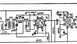
Then, the circuit initially had the following appearance:
I tested two sets of tubes, one American (6CG8´s and 6U8´s) and one European (ECF801´s and ECF80´s), with different pinouts but of electrical characteristics very close.
As a first instance, I measured the voltage developed across the grid leak resistor (10MΩ) with a DMM that has similar input resistance (and obviously a big error in the voltage read), but it was sufficient to have a roughly idea of the voltage present there and limit the signal input to a values lower than it. So, in the tubes I had at hand this value was between .7 and 1V negative. So, input signals of less than a half a volt peak was accepted. The screen dropping resistors was incremented starting with 1MΩ, and the plate resistance also increased from 100KΩ to the final values. Surprisingly, the grid leak value was altered very few tenths of millivolts during this tests. The capacitor linking both screens is there to cancel out mutually both signals present, and maintain the independence of bias for the tubes. Once the first stage satisfied me, then I let the amplifier working without signal, and with the DMM connected to the anode of the pentode, again surprising me the constancy in time and with tube replacement, the voltage there found. This also was repeated with both tube sets, with similar results.
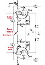
The circuit seems to be complex, but it is in essence, very simple. It can be clearly the van Scoyok essence at the first stage.
Given the constancy in the plate voltage observed, I thought in to incorporate a second stage DC coupled. With the idea of take advantage of the grid leak biasing in the second stage too, it was necessary to make the grid signal voltage as low as I could. It was evident that a SeeSaw amplifier with a high open loop gain will have a very low driving voltage. But to do such a circuit I will need a large negative DC voltage to counteract with the positive voltage found at the plate of the first amplifier. So the idea turn into the final look, say, a triode cathode follower with low output impedance, and a pentode as anode follower with low AC signal at the grid, and also low output impedance.
Both pentodes at the final stage works in the anode follower configuration or SeeSaw amplifier. The method for biasing the grids was identical to the first, say, a 10MΩ resistor where the grid contact potential is developed. This bias is also very close to –1V. As in the first stage, screen grids are resistor drop biased, and the cross-wired capacitor cancels out the signal present at those points.
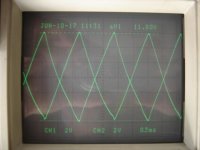
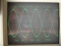
Below, some oscillograms had been taken from the circuit. Note that the original test leads for my oscilloscope, had a pin which automatically made a change in the X10 measurement (Read out), and how this devices are no longer available, then the cursors don’t make the multiplication needed. Then the amplitude of the signal must be taken ten times greater. The input high voltage was about 285V and some RC networks added in order to decouple from each one. The 1KΩ resistor at the power input only was placed there to prevent a damage to the tubes or the circuit in case of a short circuit during the manipulation of the board.


http://www.diyaudio.com/forums/attachment.php
attachmentid=631857&stc=1&d=1503580174

In the oscillograms, some minor distortion is evident in the sin and triangular waveforms, but taking into account that those distortions appears at extremely high AC output voltages where never will be pushed under normal conditions and in open loop circumstances, they are of no care, almost during firsts tests. Again, an output signal in excess of 200V from a power supply of 285V is more than satisfactory.

Some parameters measured to the prototype are:
Voltages measured without signal, with the American set of tubes:
TP1: 5.36 VDC
TP2: 4.77 VDC
+B1: 130 VDC
TP3: 31.25 VDC
TP4: 46.8 VDC
TP5: 111 VDC
TP6: 115 VDC
+B2: 276 VDC
TP7: 120 VDC
TP8: 124 VDC
TP9: -0.96 VDC
TP10: -0.67 VDC
TP11: 49.6 VDC
TP12: 34.9 VDC
+B3: 276 VDC
Ebb: 283 VDC
Measurements over TP3, TP4, TP9, TP10, TP11 Y TP12 are on high resistance circuits, comparable with the DMM input, ergo, with a big error but still effective for comparisons.
Voltages found without signal, with the European set of tubes:
TP1: 5.8 VDC
TP2: 5.1 VDC
+B1: 100 VDC
TP3: 20 VDC
TP4: 25 VDC
TP5: 150 VDC
TP6: 154 VDC
+B2: 277 VDC
TP7: 165 VDC
TP8: 167 VDC
TP9: -0.9 VDC
TP10: -0.71 VDC
TP11: 45.5 VDC
TP12: 62.5 VDC
+B3: 273 VDC
Ebb: 282 VDC
As we can see, although the tubes are different, the performance is essentially similar on both cases. Measurements have the same observation as the previously said.
Following this and this links, you can see two short videos showing the performance of the amplifier, with a sinusoidal waveform of 440Hz amplitude modulated to 100%, by another sinusoidal of 0.1Hz to see the intermediate amplifying capabilities. The former corresponds to the American set and the latter, to the European one.
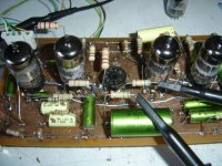
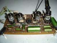
Finally, accompanying, some photos of the prototype circuit. The 3rd socket was not used in this experiment. The appearance is really ugly, but suffice for the proposed job.
Conclusions: An amplifier and phase splitter seeming the van Scoyok like, with two stages DC coupled, has been designed, build and tested, using at both of them, a grid leak (contact potential) method for biasing them, showing us the pros and cons of such configuration.
The problem with those tubes is that the triode and the pentode share a common cathode leads and pins (Although both have two cathode’s pin in the base). This precludes the use of cathode biasing for the pentode section, like in the original van Scoyok circuit.
Simultaneously I read in the Radio Designer’s Handbook (Radiotron) by Mr. Langford Smith, in two different chapters about grid leak biasing, mainly applied essentially for high mu triodes.
About the item, Langford Smith said:
But I supposed that a pentode can be considered a special case of a very high mu triode. Again, Radiotron says:
And viewing some schematics from radio receivers where this method was extensively used there, then I thought why not to test it here too.
Then, the circuit initially had the following appearance:
I tested two sets of tubes, one American (6CG8´s and 6U8´s) and one European (ECF801´s and ECF80´s), with different pinouts but of electrical characteristics very close.
As a first instance, I measured the voltage developed across the grid leak resistor (10MΩ) with a DMM that has similar input resistance (and obviously a big error in the voltage read), but it was sufficient to have a roughly idea of the voltage present there and limit the signal input to a values lower than it. So, in the tubes I had at hand this value was between .7 and 1V negative. So, input signals of less than a half a volt peak was accepted. The screen dropping resistors was incremented starting with 1MΩ, and the plate resistance also increased from 100KΩ to the final values. Surprisingly, the grid leak value was altered very few tenths of millivolts during this tests. The capacitor linking both screens is there to cancel out mutually both signals present, and maintain the independence of bias for the tubes. Once the first stage satisfied me, then I let the amplifier working without signal, and with the DMM connected to the anode of the pentode, again surprising me the constancy in time and with tube replacement, the voltage there found. This also was repeated with both tube sets, with similar results.
The circuit seems to be complex, but it is in essence, very simple. It can be clearly the van Scoyok essence at the first stage.
Given the constancy in the plate voltage observed, I thought in to incorporate a second stage DC coupled. With the idea of take advantage of the grid leak biasing in the second stage too, it was necessary to make the grid signal voltage as low as I could. It was evident that a SeeSaw amplifier with a high open loop gain will have a very low driving voltage. But to do such a circuit I will need a large negative DC voltage to counteract with the positive voltage found at the plate of the first amplifier. So the idea turn into the final look, say, a triode cathode follower with low output impedance, and a pentode as anode follower with low AC signal at the grid, and also low output impedance.
Both pentodes at the final stage works in the anode follower configuration or SeeSaw amplifier. The method for biasing the grids was identical to the first, say, a 10MΩ resistor where the grid contact potential is developed. This bias is also very close to –1V. As in the first stage, screen grids are resistor drop biased, and the cross-wired capacitor cancels out the signal present at those points.
Below, some oscillograms had been taken from the circuit. Note that the original test leads for my oscilloscope, had a pin which automatically made a change in the X10 measurement (Read out), and how this devices are no longer available, then the cursors don’t make the multiplication needed. Then the amplitude of the signal must be taken ten times greater. The input high voltage was about 285V and some RC networks added in order to decouple from each one. The 1KΩ resistor at the power input only was placed there to prevent a damage to the tubes or the circuit in case of a short circuit during the manipulation of the board.
http://www.diyaudio.com/forums/attachment.php
attachmentid=631857&stc=1&d=1503580174
In the oscillograms, some minor distortion is evident in the sin and triangular waveforms, but taking into account that those distortions appears at extremely high AC output voltages where never will be pushed under normal conditions and in open loop circumstances, they are of no care, almost during firsts tests. Again, an output signal in excess of 200V from a power supply of 285V is more than satisfactory.
Some parameters measured to the prototype are:
Voltages measured without signal, with the American set of tubes:
TP1: 5.36 VDC
TP2: 4.77 VDC
+B1: 130 VDC
TP3: 31.25 VDC
TP4: 46.8 VDC
TP5: 111 VDC
TP6: 115 VDC
+B2: 276 VDC
TP7: 120 VDC
TP8: 124 VDC
TP9: -0.96 VDC
TP10: -0.67 VDC
TP11: 49.6 VDC
TP12: 34.9 VDC
+B3: 276 VDC
Ebb: 283 VDC
Measurements over TP3, TP4, TP9, TP10, TP11 Y TP12 are on high resistance circuits, comparable with the DMM input, ergo, with a big error but still effective for comparisons.
Voltages found without signal, with the European set of tubes:
TP1: 5.8 VDC
TP2: 5.1 VDC
+B1: 100 VDC
TP3: 20 VDC
TP4: 25 VDC
TP5: 150 VDC
TP6: 154 VDC
+B2: 277 VDC
TP7: 165 VDC
TP8: 167 VDC
TP9: -0.9 VDC
TP10: -0.71 VDC
TP11: 45.5 VDC
TP12: 62.5 VDC
+B3: 273 VDC
Ebb: 282 VDC
As we can see, although the tubes are different, the performance is essentially similar on both cases. Measurements have the same observation as the previously said.
Following this and this links, you can see two short videos showing the performance of the amplifier, with a sinusoidal waveform of 440Hz amplitude modulated to 100%, by another sinusoidal of 0.1Hz to see the intermediate amplifying capabilities. The former corresponds to the American set and the latter, to the European one.
Finally, accompanying, some photos of the prototype circuit. The 3rd socket was not used in this experiment. The appearance is really ugly, but suffice for the proposed job.
Conclusions: An amplifier and phase splitter seeming the van Scoyok like, with two stages DC coupled, has been designed, build and tested, using at both of them, a grid leak (contact potential) method for biasing them, showing us the pros and cons of such configuration.
Attachments
-
 Grid Leak.GIF101.9 KB · Views: 610
 -
 Tubes.JPG146.6 KB · Views: 814
 -
 Pentode RCC.GIF6.9 KB · Views: 595
 -
 Pentode Grid Leak.GIF17.2 KB · Views: 635
 -
Van Scoyok Pentode.bmp143.7 KB · Views: 856
-
 Grid Leak 07.JPG141 KB · Views: 594
 -
 Grid Leak 06.JPG141 KB · Views: 39
 -
 Grid Leak 05.JPG134.3 KB · Views: 607
 -
 Grid Leak 04.JPG127.2 KB · Views: 599
 -
 Grid Leak 02.JPG158.9 KB · Views: 608
So what is the maximum linear swing per output? What's it look like at 100Vpp? Do you have measurements of the bandwidth, gain and phase shift?
I'm wondering how many amplifiers using this phase splitter were built commercially, I've not run across any.
Will you eventually build an amp using this splitter design or one similar to it?
Interesting project...
I'm wondering how many amplifiers using this phase splitter were built commercially, I've not run across any.
Will you eventually build an amp using this splitter design or one similar to it?
Interesting project...
Bandwidth can bee seen easily in the triangular waveform, as it contains lots of even harmonics., but a direct measure I didn't do.So what is the maximum linear swing per output? What's it look like at 100Vpp? Do you have measurements of the bandwidth, gain and phase shift?
I didn't found any previous design around this topology, say, using pentodes as a second stage, but perhaps it already exists.I'm wondering how many amplifiers using this phase splitter were built commercially, I've not run across any.
Will you eventually build an amp using this splitter design or one similar to it?
Interesting project...
May be, may not be. I'm trying differents topologies, more unusual than the usual, but still under development. But I published it because grid leak has bad reputation over DIY's and really it can perform very well.
Thanks a lot for your comments/suggestions.
> I supposed that a pentode can be considered a special case of a very high mu triode.
Mug2 of 6CG8(p) is around 20, not "high".
Yes, 10Meg will induce some bias and with 560K plate resistor and 5Meg(!) at G2 we have no worry about runaway.
However in this circuit I don't see why you can't just strap pentode G1 to ground, and trim Rg2 to get desired operating point. (However if it is working so good, don't change it!)
> grid leak has bad reputation over DIY's and really it can perform very well.
Agree here. For *small* inputs, grid-leak on high Mu triodes tends to make the most gain the tube can give. And avoids an electrolytic. The large signal performance tends to be good, though a cathode-bias affair will reliably do somewhat better. Many phono preamps grid-leak the second stage, because gain is valuable, signal levels are small compared to supply voltage, and it saves a penny.
May be, may not be. I'm trying differents topologies, more unusual than the usual, but still under development. But I published it because grid leak has bad reputation over DIY's and really it can perform very well.
Bad reputation?
No, some low noise input stages have grid bias, with deadly grounded cathodes.

R12 and R14 are feedback resistors. They convert the output pentode into an anode follower while the upper triode acts a cathode follower, both having near 1 gain. If you remove those R's, the pentode section no longer acts as a seesaw amplifier, and no longer the grid voltage is low. In this case, the distortion will increase severely because of grid current, and unpair action of both output devices.
Hi Osvaldo,
would you like to share the schematics of your PI? As far as I am informed, the van Scoyoc PI originally comprises four triodes, but I have also seen designs around six triodes (by Alfred Zechendorff in the German FUNKSCHAU magazine, about 1954). Your pics show four valves. Are all these triode-pentodes?
Edit 1: Ah, now I see your drawing, which answers all of my questions!
Edit 2: PCF200 and PCF201 are very similar valves, but with pentodes of high µ low-noise frame grid design. The latter one shows remote cut-off characteristics. Both feature a 10 pin Decal base, though, which was not very common outside Europe. Their cathodes are brought out on individual Pins, like ECF80 and ECF802.
Best regards!
Last edited:
R12 and R14 are feedback resistors. They convert the output pentode into an anode follower while the upper triode acts a cathode follower, both having near 1 gain. If you remove those R's, the pentode section no longer acts as a seesaw amplifier, and no longer the grid voltage is low. In this case, the distortion will increase severely because of grid current, and unpair action of both output devices.
This is what i mean.Mona
Attachments
The different output signal levels, albeit a small difference and presumably resulting from it's rather low signal gain, unfortunately is one of the disadvantages of the van Scoyoc phase splitter. Your workaround is well covered in the second paper behind this link: http://www.pearl-hifi.com/06_Lit_Archive/07_Misc_Downloads/Cross-coupled_Phase_Inv_Comp.pdfYeah, I tested it. The only difference is half the output voltage. A tiny difference between outputs, but an trimmer may be added in the circuit.
Best regards!
Yes, I already had a copy of this paper.
One of the intentions of make this amp, and that I forgot to write in the first post, was to test the claimed bad common mode rejection ratio of the van Scoyok circuit, which is in true, not too good as a differential pair with a CCS. What I still have as a doubt, is which is the relation between output imbalance and CMRR in a differential circuit. This is one of the current projects I'm working in.
One of the intentions of make this amp, and that I forgot to write in the first post, was to test the claimed bad common mode rejection ratio of the van Scoyok circuit, which is in true, not too good as a differential pair with a CCS. What I still have as a doubt, is which is the relation between output imbalance and CMRR in a differential circuit. This is one of the current projects I'm working in.
When designing my Circlotron monoblocks about fifteen years ago, I first tried the original 6SN7-6SL7 van Scoyoc PI, followed by another 6SN7 as a symmetric voltage amplifier that drives the PL519/40KG6A finals. Unfortunately, the frequency response at the upper end was bad. So I swapped for an also cross-coupled design that I've found at Andrea Buonavolta's site. This features two 12AT7's in Cascode mode. Result was better, but still not good. Eventually, I discarded the van Scoyoc in favour of a LTP PI with two 6922's in Cascode, which is satisfying now.
Best regards!
Best regards!
Interesting. My current project includes a pair of EF184 with a ECC84 cascoded as a CCS. About 24MR in my calculus, of cathode resistance. Notoriously better than the vS, it has about 2000:1 of CMRR. A second stage of ECL84's with another ECC84 still improves it. But, in between I found in http://www.extra.research.philips.com/hera/people/aarts/_Philips Bound Archive/PTechReview/ an interestig series of aticles in where some considerations of differential pairs refers, where I borrowed some ideas, the CCS cascoded, for example. But I still found differences between outputs. I would want to test how feedforwarding the circuit, to get "autostabilization". One idea that worked more or less good, was to use the suppressors grid of EF184's as a second grid, where a NFB loop is closed. And it is encouraging, but it will be material for other thread.
- Status
- This old topic is closed. If you want to reopen this topic, contact a moderator using the "Report Post" button.
- Home
- Amplifiers
- Tubes / Valves
- A Grid leak-Van Scoyok Phase splitter