Hi there,
I am looking for a differential to SE building block, to be used inside a frequency synthesizer.
This is a bare bone example of such an archetypal circuit:
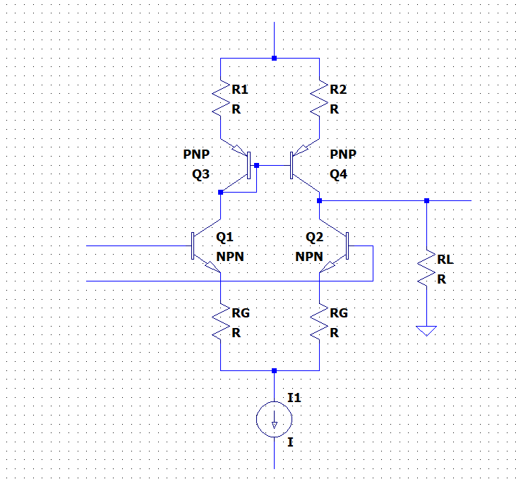
It should have a good linearity (preferably better than 1ppm), a moderately wideband (1MHz), but it should retain its performances flat for the whole frequency range, and in particular have good IMD performance, even for frequencies above its range.
And it should be reasonably simple of course: it is always possible to solve that kind of problem by throwing lots of transistors at it, but I don't need the luminaries of DIYaudio to do that.
A possibility is to use a Xquad variant, as in the input stage of the Tringlinator, but raw performances and bandwidth are borderline for this application.
Edmond Stuart has nice topologies that could be adapted for my purpose, but they are complex, because they are intended to be used in a FB context, with compensations, and this complicates matters uselessly for me.
Any better ideas?
I am looking for a differential to SE building block, to be used inside a frequency synthesizer.
This is a bare bone example of such an archetypal circuit:
It should have a good linearity (preferably better than 1ppm), a moderately wideband (1MHz), but it should retain its performances flat for the whole frequency range, and in particular have good IMD performance, even for frequencies above its range.
And it should be reasonably simple of course: it is always possible to solve that kind of problem by throwing lots of transistors at it, but I don't need the luminaries of DIYaudio to do that.
A possibility is to use a Xquad variant, as in the input stage of the Tringlinator, but raw performances and bandwidth are borderline for this application.
Edmond Stuart has nice topologies that could be adapted for my purpose, but they are complex, because they are intended to be used in a FB context, with compensations, and this complicates matters uselessly for me.
Any better ideas?
Attachments
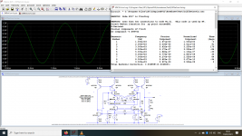
Whilst making tests, I stumbled upon an unexpected effect.
Normally, increasing the loading of an amplifier leads to an increased distortion, but there are sometimes exceptions.
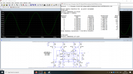
This circuit is such an example. Here, without the 3K3 output load, the THD reaches ~48ppm:
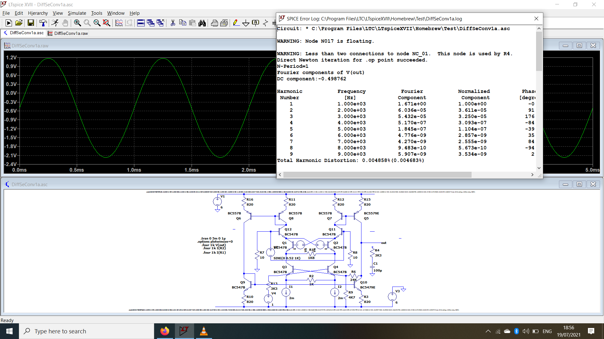
When the 3K3 is connected, and the input level is readjusted to compensate for the drop (the circuit doesn't have an output buffer yet), the THD becomes 17ppm:
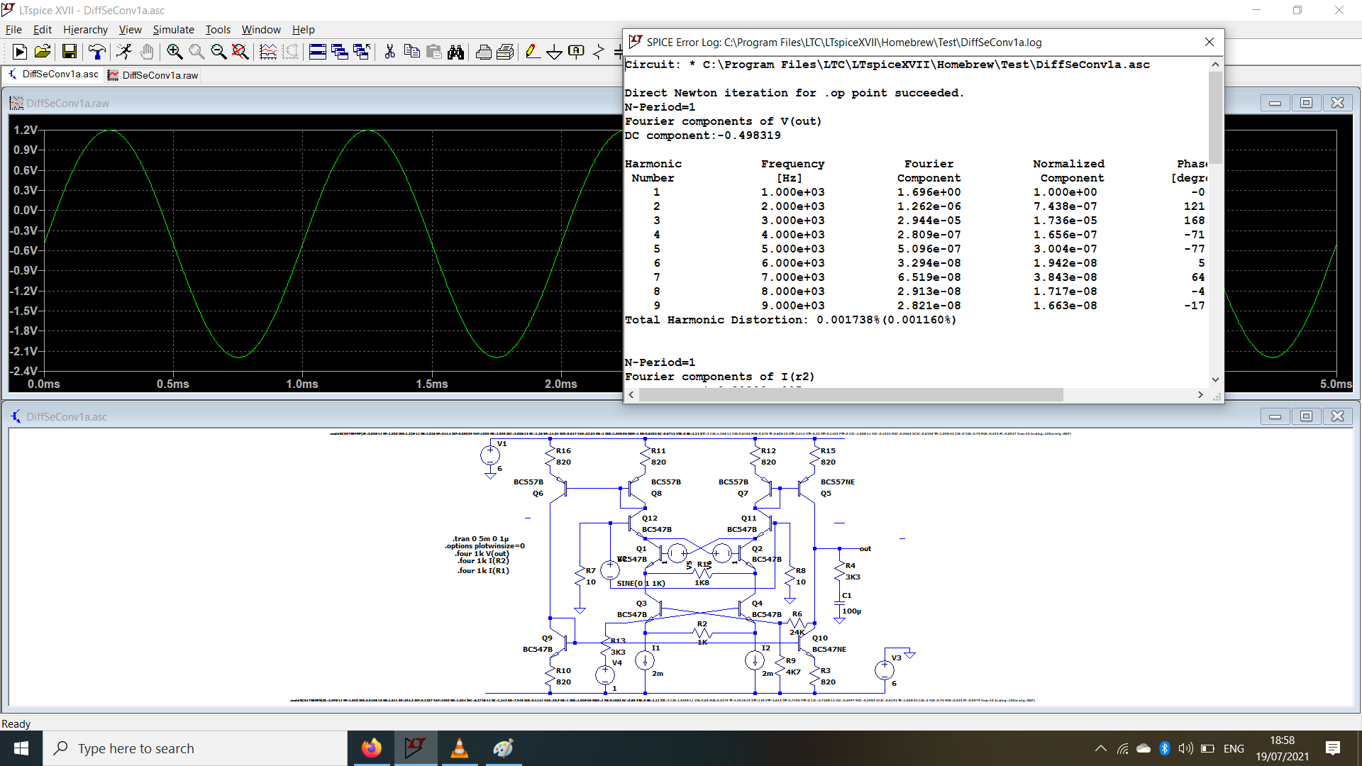
This is rather remarkable: the load is heavier, the input signal is larger, yet the linearity is improved.
The strangest is that this circuit is not really an exception: I have tested (in the real world this time) a number of ppm-capable opamps, in the LM4562, NE5534 league, and a significant proportion displayed a similar behaviour.
Others reacted as expected.
My interpretation is that the distortion mechanism has a higher internal impedance than the linear amplification, and is more affected by the output shunting.
Any opinions/observations about that?
Normally, increasing the loading of an amplifier leads to an increased distortion, but there are sometimes exceptions.
This circuit is such an example. Here, without the 3K3 output load, the THD reaches ~48ppm:
When the 3K3 is connected, and the input level is readjusted to compensate for the drop (the circuit doesn't have an output buffer yet), the THD becomes 17ppm:
This is rather remarkable: the load is heavier, the input signal is larger, yet the linearity is improved.
The strangest is that this circuit is not really an exception: I have tested (in the real world this time) a number of ppm-capable opamps, in the LM4562, NE5534 league, and a significant proportion displayed a similar behaviour.
Others reacted as expected.
My interpretation is that the distortion mechanism has a higher internal impedance than the linear amplification, and is more affected by the output shunting.
Any opinions/observations about that?
Attachments
Just a guess. There’s negative feedback there, without compensation.
It may go unstable without the load.
It may go unstable without the load.
If you google Barrie Gilbert +opamp +diffamp or some similar description, you may find something useful.
It is a sim, and it is easy to see that no oscillations are present.Just a guess. There’s negative feedback there, without compensation.
It may go unstable without the load.
The opamps I tested in reality were used in a completely normal way, and they didn't oscillate either, yet the counterintuitive behaviour with a load was also present (in some cases)
Thanks for the tipIf you google Barrie Gilbert +opamp +diffamp or some similar description, you may find something useful.
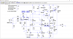
This is the final version of the circuit I opted for:

It is moderately complex, has a comfortable sub-ppm linearity, a multi-MHz bandwidth and a good time-domain response.
It is an hybrid between a X-quad input and an E. Stuart topology.
I post it, as it it could be useful to other members. It is rather specialized though: it is shown in its bal to SE configuration, and it could be used in other tasks/configurations, but it is severely restricted, mainly because of the X-quad: it has a negative impedance, and if the impedance between the + and - inputs exceeds ~2*Re*Hfe, it becomes unstable.
If this condition is respected, it can be used in other tasks like a regular discrete opamp, but the input impedance will always need to be low.
The values and components on the schematic are those used in the sim, those in brackets are the ones I used for the real circuit.
I opted for the S9014/9015 because they have a lower capacitance, a higher Vaf and a higher Ft than the BC's (although they are cheap Chinese)
Attachments
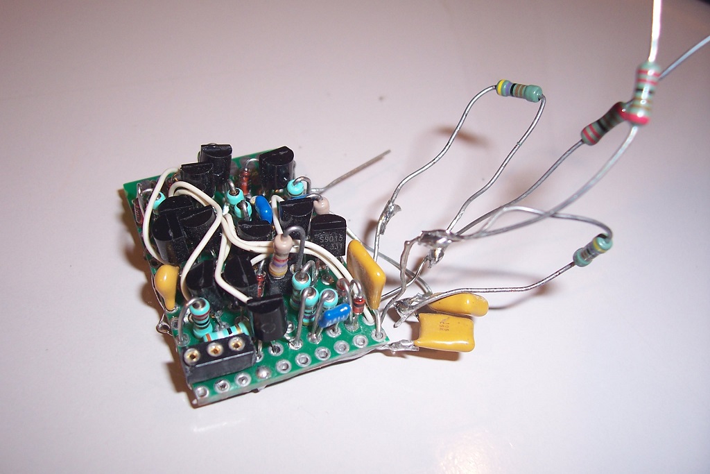
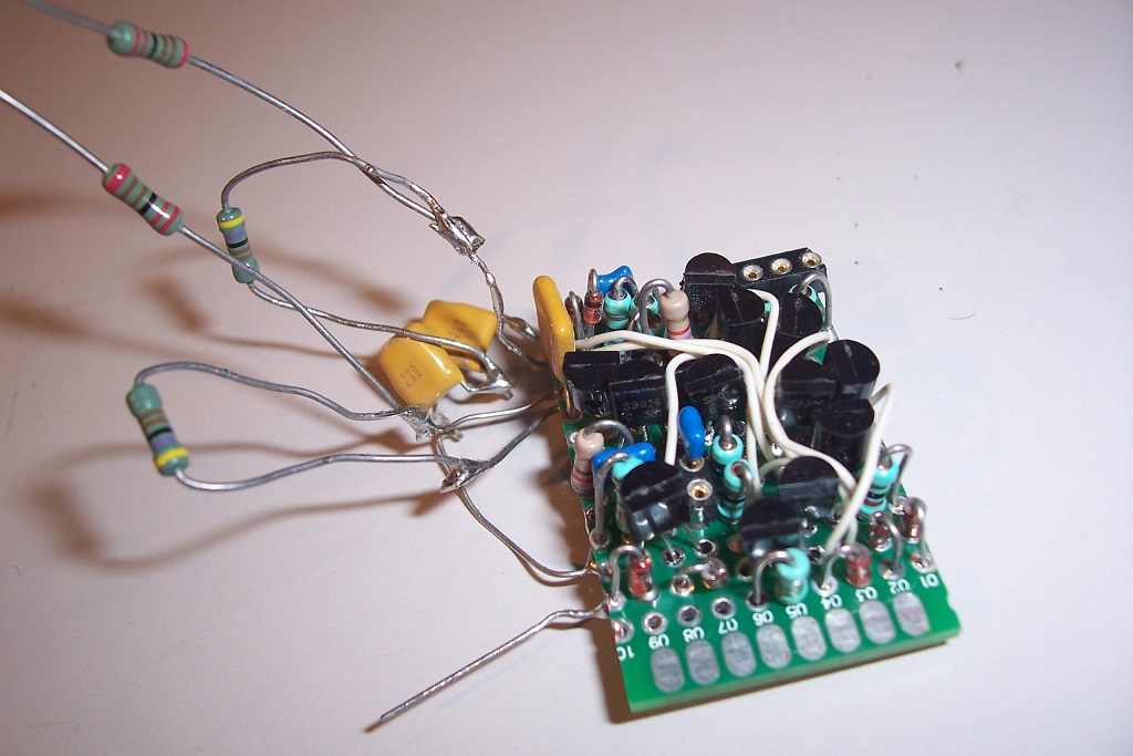
This is the opamp module:
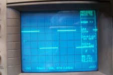
And this is the 100kHz squarewave response:

In order to achieve such a level of cleanliness, the compensations need to be tweaked quite accurately.
They are suited to the gain of ~2.2, but they would need to be readjusted for other values.
Unity gain stability would probably be difficult to achieve (I didn't test it, I just need the 2.2 gain)
And this is the 100kHz squarewave response:
In order to achieve such a level of cleanliness, the compensations need to be tweaked quite accurately.
They are suited to the gain of ~2.2, but they would need to be readjusted for other values.
Unity gain stability would probably be difficult to achieve (I didn't test it, I just need the 2.2 gain)
Attachments


" inputs exceeds ~2*Re*Hfe, it becomes unstable"
Is Re here R1 and R2, emitter degeneration resistors of the input stage?
Is Re here R1 and R2, emitter degeneration resistors of the input stage?
- Home
- Amplifiers
- Solid State
- A good unbalancer suggestion?