pacificblue said:Yes. Did you check the heatsinking you need?
Something around 1,7K/W on each chip?
Where do the 80-100VA/channel come from?
From the "power supply for beginners"-guide. Isn't that correct? I didn't understand how to calculate it, so I just went for the recommended.
Depends on your source and the input resistance you use. It will work that way, if the combined impedance is not too low for the driving source. An input buffer in between is of course a more elegant solution.
I'm not quite following you hear. Can you please explain a bit more?
The input buffer, what does it do? Just "copy" the current/voltage?
Would give you a peak temperature difference of 45°. Good solution.Ulew said:Something around 1,7K/W on each chip?
It is one way of solving it. The easiest way to calculate a transformer is to make it as big as the expected output power, and rely on the power supply capacitors to do the rest. The transformer may be driven into saturation, when it has to recharge the capacitors. People, who have experimented with it found out that using a transformer of three times that size guarantees that no negative audible effect results from that.Ulew said:From the "power supply for beginners"-guide. Isn't that correct? I didn't understand how to calculate it, so I just went for the recommended.
Your solution is a compromise in between, so nothing wrong with that.
In this case it could provide the correct load for your driving source (CD player, MP3 player, etc.) and at the same time be a sufficiently powerful driver for the paralleled LM3886 inputs. Remember Ohms law again U=RxI. You set R by chosing Rin for your LM3886. Then you want to use two LM3886 inputs in parallel, so R is halved and I must be doubled to maintain the voltage level. If your source has not enough muscle to deliver that amount of current the signal gets distorted.Ulew said:I'm not quite following you hear. Can you please explain a bit more?
The input buffer, what does it do? Just "copy" the current/voltage?
To say it in your words, the buffer copies the voltage and provides the necessary current. As a side effect you can easily convert it into a voltage amplifier aka pre-amplifier to help out, if your sources don't provide enough output voltage swing in the first place.
Investigate the Overture Design Guide excel spreadsheet. It allows you to put in values (like power supply DC voltage) and will tell you power output, heatsink requirements, etc. Be aware that if it tells you the required heatsink is too large you will probably need a fan (or just lower the power supply voltage).
pacificblue said:
...Then you want to use two LM3886 inputs in parallel, so R is halved and I must be doubled to maintain the voltage level....
Oh, I didn't mean the input for the amp, I meant the transformer! If it's possible to make an 2X24V to an 4x24 by just adding two cables from the output of the transformer!
You can use one transformer to supply as many amps in parallel as the power rating allows.Ulew said:I meant the transformer! If it's possible to make an 2X24V to an 4x24 by just adding two cables from the output of the transformer!
pacificblue said:
You can use one transformer to supply as many amps in parallel as the power rating allows.
So the answer is yes?
no.Ulew said:So the answer is yes?
He said you can parallel as many loads as you want upto the rating of the transformer.
adding two wires does not convert a dual secondary to a four secondary transformer.
You can add two extra windings to create a four secondary but you will probably run out of room fitting in all that extra copper.
pacificblue said:
You can use one transformer to supply as many amps in parallel as the power rating allows.
no, just add as many amplifiers in parallel upto the rating of the transformer.Ulew said:Okay, so then I need two transformers..
AndrewT said:
no, just add as many amplifiers in parallel upto the rating of the transformer.
But that's what I mean! (I think 😉 That you but two amps in parallel so you can power two amps from one output on the transformer!
this confused us and you.Ulew said:
Oh, I didn't mean the input for the amp, I meant the transformer! If it's possible to make an 2X24V to an 4x24 by just adding two cables from the output of the transformer!
You cannot convert a dual secondary to a quad secondary by just adding two wires. You need to add two extra windings to create the third and fourth secondaries.
You can tap off the existing windings to a second and even a third PSU.
Alternatively tap off the existing PSU to supply the second amplifier.
AndrewT said:this confused us and you.
Actually, I was confused before writing that! 😉
You can tap off the existing windings to a second and even a third PSU.
Alternatively tap off the existing PSU to supply the second amplifier.
Great!
Here is another one...
"A PCB can always be improved" is the thing i learned when i further modify my existing freezed single layer PCb for lm4780.
It has only 4 jumpers. 1 in +V, 2 in ground supply and 1 in mute circuit.
Rin1, Rin2 and RGnd will come on track side. And Ground conenctions for speakers will be taken from power supply board.
(All components named with reference to lm4780 datasheet)
Attachments

Re: Here is another one...
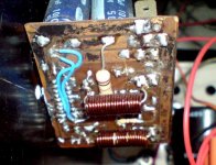
That one looks nice! What are those two big pink things connecting the output?
kuldeepsingh said:"A PCB can always be improved"...
That one looks nice! What are those two big pink things connecting the output?
Re: Re: Here is another one...
Output inductor with output resistor inside.
Ulew said:
That one looks nice! What are those two big pink things connecting the output?
Output inductor with output resistor inside.
Attachments
- Status
- Not open for further replies.
- Home
- Amplifiers
- Chip Amps
- A good single sided PCB for bridged LM4780?